David's Astronomy Pages
CCD Image Notes - Session 78 (2004-12-07)
Notes
(S71)
Notes
(Main)
Home
Page
Notes
(S81)
David's Astronomy Pages
|
Notes (S71) |
Notes (Main) |
Home Page |
Notes (S81) |
Sessions 76 to 78 were largely devoted to improving the Polar Alignment of my permanently mounted LX200 scope , to analysing the scope RA drive performance and to retraining the scopes periodic error correction (PEC). During the period existing software scripts were updated and extended to help facilitate these tasks.
My LX200 scope is equatorially mounted on a wedge mounted on top of a metal permanent pier, which is bolted to a concrete base dug in the ground. When first fitted in its new Clair Observatory in February 2004 the scope was aligned on the Pole Star (Polaris) and then a quick Drift Star run was used to provide an improved (but still fairly rough) Polar Alignment.
Whilst TPoint Software was used to successfully improve Telescope pointing during Sessions 56-75, misalignment of the scope's polar axis was found to cause stars to begin to drift in images longer than 1 minute exposure and to cause the objects to gradually drift away from the image centre when taking a series of images. Although autoguiding can be used to eliminate these problems it is not always possible to find a suitable guidestar and in any case autoguiding requires more preparation and setting up. The mitigation that was generally used was to take shorter exposure images (60s or less) and to align the individual frames before combining them. The downside of the latter approach is that the area of full data coverage becomes smaller and smaller with time (and of course evenutually the target bject will eventually drift out of frame, requiring that some form of target re-centering is employed)
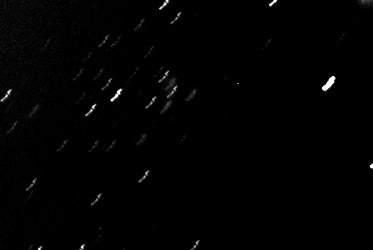
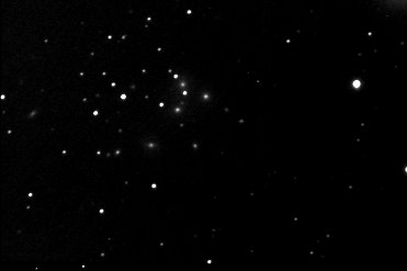
The following example from Session 71 shows the impact of the scope's polar misalignment, together with evidence of the reasonably successfully application of frame alignment before combination. Note that the wiggle in the star trails is most probable residual periodic error (after PEC).
| Example Image prior to Fine-Tuning the Polar Alignment (NGC 70 Galaxy Cluster) | ||
|
|
|
|
~10min Combined Exposure without alignment of individual frames. 9 x 60s (average combine) 2004-09-07 (#71041-49), Decl'n +30 deg |
Image as left, with alignment of individual frames |
|
Analysis of TPoint run made during session 72 showed that the Scopes Polar Axis was out by around 22 arc mins (I needed to move the Scope's Polar Axis East by 15.5 arc mins and raise it by 15.7 arc mins). I decided that I would make the necessary adjustments to the scope's wedge during a future session.
Back to Top
An issue when making adjustments to the Telescope Wedge is knowing how much one is raising/lowering it or how much one is rotating it. e.g. how much manual rotation of the wedge will give a required rotation of 15.5 mins.
One method that I read on the web (sorry I didn't note the reference) was to attach a lasar pointer to scope and then use the distance from the lasar pointer to the illuminated lasar dot, the required angle of change and a little trigonometry to calculate the distance that lasar dot needs to shifted.
The method seemed suitable to my needs and I acquired a lasar pointer (one those DIY pointers used for levelling - it's about 25 x 4 x1.5 cm in size) and wrote an Excel Worksheet to calculate the lasar point adjustments from inputs such as the polar-axis misalignment angles.
Some trial adjustments were made using the lasar pointer method during session 65-66 which proved the concept. The motion of lasar dot was measured on a piece of graph paper (1 mm squares) fixed on the south wall of the observatory. The starting point for the dot was marked and adjustments made to the wedge until the dot had moved the required number of millimetres.
Session 76 was due to have been the session in which the improved wedge adjustments were made. However the session was a big disaster and caused me to introduce a 4 degree error in the Polar Axis position, which had to be fixed during Session 77.
Five main problems were encountered. These and the solutions
adopted are listed below.
(Note : the descriptions and fixes refer to those appropriate in the North
Hemisphere).
i) the laser pointer would gradually droop causing the
lasar point to move by itself
I used insulating tape to temporarily attach the pointer to
the scope, however this was simply not up to the task, as the tape simply
wouldn't stick adequately to cold metal in the presence of condensation.
Solution : I used a DIY Gripper to grip the laser point to the the bottom
part of one of the fork arms. This gave the necessary secure connection, yet
allowed the easily removal/reconnection of the pointer when required.
ii) the laser pointer was initially not appropriate connected to the scope
I initially connected the laser pointed to the wedge base instead of the scope itself. Whilst this was ok for measuring rotations of the wedge, when I went to adjust drop the wedge inclination I found that even though I was turning the wedge knob and the polar axis of the scope was raising the laser dot stayed fixed on the same point on the wall. Without a reference to go by I found that I had an inadvertently knocked the scopes polar axis out by 4 degrees.
Solution : I analysed what had gone wrong and then subsequently made sure that the laser pointer was always attached to the scope forks, so that the motions of the laser dot would always be consistent with motions of the wedge.
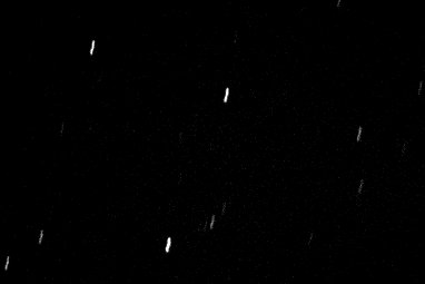
| Significant star trailing caused by a 4 deg
misalignment of polar axis (Drift rate is 1.8 arc min/min) |
|
| CCD Image, 15 sec exposure (#76012) |
iii) the laser dot was initially moved the wrong way in azmiuth and in inclination
I was working with the laser light pointing onto the south wall of the observatory. When I needed to move the polar axis east, I initially took this literally as meaning that the laser dot should be moved east (of course when facing south this gives a anticlockwise movement when I should have been making a clockwise movement).
Similarly when I need to raise the polar axis I initially took this literally as meaning the laser dot should be raised , when in fact the opposite was required.
Solution : I revised my worksheet to describe the required azimuth movement of the wedge clearly as either a Clockwise rotation (Right on the South Wall) or a Anticlockwise rotation (Left on the South Wall) and to describe the required inclination movements correctly as either raise laser dot or lower laser dot.
iv) measurement of the wedge adjustments is difficult if scope is operating
When operating the telescope will track the stars at the sidereal rate (causing the laser dot to clockwise at a rate of 15 arc minutes per minute. This makes it difficult to measure the relative adjustments made to the wedge.
Solution : I found that turning off the LX200 scope was the only way to ensure that the required adjustments to the scope's polar direction axis were correctly implemented
v) the technique was unable to give me better than 5 arc mins accuracy
In my observatory I'm limited to a maximum laser pointing length of around 70 cm (the distance from the scope to the wall of observatory). Given that laser dot is around 2mm in diameter it is not feasible to make adjustments to better than +/- 1mm accuracy. This is equivalent to around 5 arc mins in Polar Alignment. [Note: higher accuracy could be achieved if a greater laser ranging distance was available, eg if a 2m distance was available a accuracy of ~1.8 arc mins could theoretically be obtained]
Solution: For better than 5 arc min accuracy a different method was needed. Instead of the laser dot the stars themselves can be used as a reference for tracking the adjustments. This is described in section below.
Back to Top
As described above making Wedge Adjustments using LASER Pointing Reference was used to make coarse adjustment corrections to the Polar Axis Alignment. However for improvements better than 5 arc mins accuracy a different approach was required.
It was realised that Stars themselves could provide the best
reference for aligning the scope.
A script was written that would firstly allow a Base Image to be taken and the
initial Celestial position determined by Image Linking. Appropriate
adjustments to Wedge Azimuth and Inclination are then made to correct in the
right directions (must be careful here). To assess progress in adjustments Check
Images can then be taken with the script from which it determines and reports
the relative motion of the Celestial Position. Wedge Adjustments are
continued until the required corrections are produced. As a back-up the
Brightest Object Position is also determined and reported.
[ Continuous image frames could also be taken to show the progress ]
It is considered that this approach is best used where the corrections required are sufficiently small that they will keep a reference star or star group visible on the CCD Frame (say less than 5-10 arc mins). If larger corrections are needed there would be a danger of moving into sparse star area and it may be not be possible to measure the new celestrial position or return to the original position.
Back to Top
The progressive improvement in Polar Alignment made during Session 77 is shown in the table below. After 4 adjustments of the wedge innclination and azimuth, total polar axis misalignment was reduced from 4.1 arc deg down to 3.3 arc minutes.
| Polar Axis Inclination |
Polar Axis Azimuth |
||||||||
| Wedge Adjustment | 1st | 2nd | 3rd | 4th | 1st | 2nd | 3rd | ||
| Image Pair | #77001/02 | #77007/08 | #77020/21 | #77022/23 | #77003/04 | #77015/16 | #77018/19 | ||
| Sky Region | SOUTH | SOUTH | SOUTH | SOUTH | WEST | WEST | WEST | ||
| Declination | deg | 0 | 0 | 0 | 0 | 15 | 15 | 13 | |
| Drift Direction | N or S | n | n | n | n | n | n | n | |
| Drift Rate | arc secs/min | 8.74 | 3.18 | 1.38 | 0.62 | 61.76 | 4.70 | 0.59 | |
| Est. Drift rate at 0 Dec | arc secs/min | 8.74 | 3.18 | 1.38 | 0.62 | 63.94 | 4.87 | 0.61 | |
| Misalignment | arc mins | 33.4 | 12.1 | 5.3 | 2.4 | 244.2 | 18.58 | 2.3 | |
Back to Top
With improved polar alignment individual frames can be of much
longer exposure time, as stars taken
longer to drift from one pixel to another. The full image area can be
maintained for longer and target objects can be retained on the image frame
for significantly longer.
| Example '10 min' Image before Fine-Tuning the Polar Alignment (NGC 70 Galaxy Cluster) |
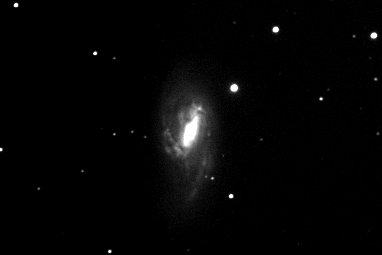
Example '10 min' Image after Fine-Tuning the Polar Alignment (M66 Galaxy) |
|
|
|
|
|
|
~10min Combined Exposure (no autoguiding / no alignment of individual frames) 9 x 60s (average combine) 2004-09-07 (#71041-49), Decl'n +30 deg |
~10min Combined Exposure (no autoguiding / no alignment of individual frames) 5 x 2 min (average combine) 2004-12-11 (#79010-14). Decl'n +13 deg |
Back to Top
Every self-tracking scope will suffer from a degree of periodic error, associated with mechanical imperfections in the turning equipment. The LX200 is no different and suffers a fair amount of periodic error due to the worm drive which turns the RA drive in ~ 8 minute cycles. The error on LX200 scopes is typically up to around +/- 25 arc secs (40-60 arc secs total movement). On my scope I've measured the periodic error as being around 55 arc secs during session 77. This was consistent with some previous measurements made in 2001-2002.
| Periodic Error of 55 arc secs in RA measured during an 8 min period |
|
CCD Composite (av78 x 0.5s) Click for Animation |
Fortunately the LX200 has a means of correcting the periodic error (known as PEC ), but to do this it must be trained. This is done by guiding on a star for the duration of a full 8 min cycle of the worn drive, during which the the scope learns whether to speed up or slow down the RA tracking during each of 200 periods of time (200 x 2.4 second periods). The LX200 also has the facility (Update) to improve the PEC by guiding on a star for a further 8 minutes.
The PEC training on my scope was originally performed by visually watching a star through the eyepiece and guiding E-W manually using the LX200 control pad. This is fairly tedious to perform and CCDSoft's Autoguider Software can be used to automatically measure the changes in a star's position and guide the scope to re-centre the star. In the past attempts I 've made some half attempts at using the Autoguider for training the PEC in this way, however the results had proved less satisfactory than with manually training.
Through reading of other peoples experience of using Autoguiders by PEC training of LX200 scopes, I set out to achieve at comparable or better results with auto-guide training than I could with manual training. This was performed during Sessions 77 and 78.
The key success factors seem to be
i) choose a night when seeing is good
ii) get the scope reasonably polar aligned first (such that Dec Drift is
minimal over an 8 min period and star will stay within the autoguider's 32x32
pixel window)
iii) align the CCD camera with celestrial N-S/E-W axes
iv) find a reasonable bright star close to Dec 0, calibrate the Autoguider
and guide of star (any periodic errors will be most obvious at Dec 0, a bright
star will allow exposures times to be short, allowing the telescope to be guided to the star's new position as quickly
as possible after an RA fluctuation occurs)
vi) ensure that guiding corrections in Dec are turned off (we only need to work
with RA guide corrections - Dec corrections can cause un-required RA changes)
I found that with 0.10 sec exposures I can get a picture taken, analysed and guide corrections made about once every 5 secs (it is probably best that AutoSave images is turned off to save time). Due to scintillation and apparent movement of star due to varying atmospheric refraction, taking slightly longer images might smooth out the 'seeing', e.g. a 0.3 sec image would add minimal extra time to the 'cycle' time, yet represent a x3 increase in exposure, compared to a 0.1 sec image. Logging the autoguiding data is useful in order to later analyse the corrections made, but may slow up the 'cycle' time.
The results of impact of PEC training, using two 8 min training sessions, is shown in the images below.
| SAO 132086 (Orion) (Dec. -0 deg 30 min, Mag +6.6) |
||
| Record of RA
Fluctuation without PEC 'Large RA fluctuations' |
Record of RA
Fluctuation with PEC (post-training) ' Minor RA fluctuations' |
|
|
CCD Composite (av78 x 0.5s) Click for Animation |
CCD Composite (av78 x 0.5s) Click for Animation |
|
Back to Top
Following PEC Training, the RA and Dec Drift of a reasonably bright star close to Declination 0 deg was analysed over an 8 min period (the length of one rotation of the worm drive). This was performing using CCDSoft's Autoguide facility with the X and Y Relays turned off allowing the apparent movement of the star can be recorded. The X and Y drift (in pixels) was converted to drift in arc secs using the known image scale. (1.25 arc secs/pixel in this case).
|
RA and Dec drift of Mag +2.2 star Mintaka (Dec -0deg 18min, Orion) (using 1x1 binned images at 0.1 sec exposure) |
||
The RA Drift shows a residual periodic error of approximately 2.5 arc secs (not perfect, but considerably better than 50 arc sec error without PEC). Most of the smaller high frequency fluctuations (~1.5 arc sec) are probably mainly related to the effects of 'seeing' (varying atmospheric refraction). The fluctuations appear slightly larger in RA than Dec suggesting there is also a contribution from high frequency periodic or random errors in the RA Drive. [ not sure if any of the high frequency fluctuations could be due to vibration of the scope by either the CCD Fan or by the RA drive train ]
It can be seen that there is some declination drift occuring. This is in the order of 1.4 arc secs over the 8 min period, 0.17 arc secs per minute, and is equivalent to a polar axis misalignment in the order of 0.7 arc minutes. The mean drift is indicated by the red line in the above chart. The green lines reflect the +/- 0.7 arc variation (total variation 1.4 arc secs) which can probably be attributed to seeing.
By creating a moving average through the RA data (purple lines) the residual periodic error in RA drive is shown to be around 2.5 arc secs. By adding +/- 0.7 arc sec 'seeing variation' it appears that there are a number of higher frequency periodic or random RA drive errors. Equally these may be positions where training has inadequately corrected the largest (faster moving) RA periodic errors.
A moving average through the Dec Data (purple line) suggest a variation of around 0.4 arc secs at intervals of around 1.2 to 1.8 minutes. This might be related to low frequency atmospheric effects or an effect related to the RA drive.
Back to Top
| Artifacts around Saturn |
|
|
CCD Image 1 sec, C Filter 2004-12-03 (#77285) |
| Artifacts around Hamal (Aries) |
|
|
CCD Image 15 sec, C Filter 2004-12-07 20:23 h UT (#78001) |
Back to Top
| This Web Page: | CCD Image Notes - Session 78 (2004-12-07) |
| Last Updated : | 2015-05-16 |
| Site Owner : | David Richards |
| Home Page : | David's Astronomy Web Site |