David's Astronomy Pages
|
Notes (S324) |
Notes (Main) |
Home Page |
Notes (S355) |
|
Ted Agos Universal Focal Reducer Adapter Tube ST-10 XME CCD Tests, Gain, ReadOut Noise, Dark Current Cosmic Rays / other radioactive decays >
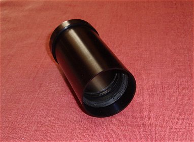
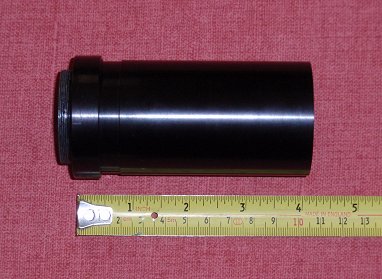
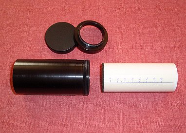
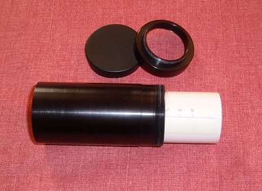
In early 2009 I purchased a Ted Agos Universal Adapter Tube fitted with an Antares focal reducer. This will become a main part of my new imaging setup from 2009 onwards.
|
Ted Agos Adapter Tube fitted with Antares 6.3 focal reducer |
|
The advantages of the Adapter tube are several
The Focal Reducer was tried out for the first time during session S351.
Experiences are listed below
So there we go. My overall feedback is that a) you may wish to note the warning regarding the issue of using Adapter with Optec TC-S and 8" LX200 b) you might consider whether to use a slightly shorter tube (or promote a shorter tube option in such cases) Some of the above issues will (should) go when I moved to 12" LX200, ST-10 combination (they're ready to move into my observatory with its new taller roof).
Overall I think I'm happy with the Adapter tube (or at least will be shortly)
If I was staying with my 8" LX200 I think I would be looking to cut around 15mm off the bottom end of the adapter tube with a hack saw (or better still in a machine workshop)
Moving forward. I was wondering about the vignetting issue which I'm already seeing with my smaller ST-7e camera (if vignetting is what the problem is). The issue might simply reduce or be eliminated by adjusting the focal reducer spacing to a more optimum position, as this has large effects as you have documented. I'm a bit concerned however that if/when I move to using a AO-8 unit (when I will push the reducer up to the AO-8 end of the adapter tube to reduce the extra spacing to its minimum), I will be left with long section of tune before the adapter with its less than 2" ID (1-7/8" ID ?), which might cause more vignetting than a shorter tube, where I would have access to full 2" or 2.5" of aperture at the back of the scope. So I still might need to cut off the end of the Adapter tube.
|
Ted Agos Adapter Tube fitted with
Antares 6.3 focal reducer |
|
|
|
|
|
|
|
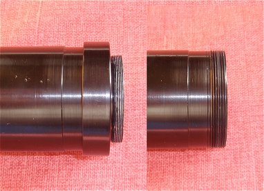
T-Threads lightly filed (left), Tube without End-Shoulder (right) |
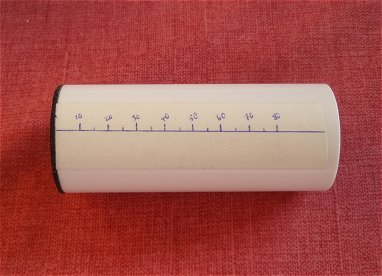
Push Rod, modified with simple scale bar (mm) |
|
|
|
|
|
Adapter with End-Shoulder removed |
Push Rod inserted into Tube to move sliding insert |
|
|
|
|
Back to Top
A series of tests were performed on my new ST-10XME CCD camera on/around 2009-02-18 to 27, with the goal of characterising the performance the camera to confirm its general health and provide parameters to input into advanced photometric SNR calculations.
The ST-10XME camera is 16 bit, and uses the KAF
3200ME CCD. This is a Non-ABG CCD and has is specified as having high QE (peak
QE 85%) due to micro lens over each pixel. and low dark current,
The full well capacity is understood to be 77,000 e-
and gain is 1.32 e-/ADU.
The camera is specified to have a dark current of 0.5e-/pixel/sec at 0 deg C
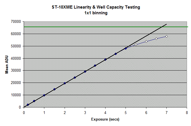
At 1x1 binning, saturation level in the camera was measured to be around
x ADU. This compares with an expected figure of ~58333 ADU.
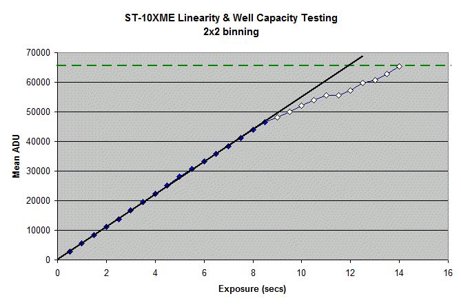
At 2x2 binning, saturation level in camera is ~ x ADU. This compares
well with the expected value of ~x ADU
A basic CCD test was conducted based around the methodology given in "The Handbook of Astronomical Image Processing", Section 8.2 by Richard Berry and James Burnell [http://www.willbell.com/aip/index.htm]
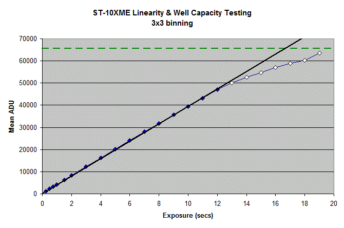
The flats were taken using white illuminated board on the wall of the observatory and a tungsten light source, with the integration time selected to provide a suitable Flat Frame count; around 50% of saturation level. 2x2 is the normal binning mode that I use for taking light frames at night. Frames were also collected at 1x1 and 3x3 binning for comparison.
In practice 3 flat, 3 bias and 3 dark frames were taken allowing 3 pairs of
bias and flat frames to be created.
Manipulation of Frames (Mean and Standard Deviation)
Frames were analysed using AIP4WIN. (AIP4WIN software is available with the "The Handbook of Astronomical Image Processing". It has superior analysis tools compared to those of CCDsoft )
The two bias frames were added together and the mean pixel value was measured μ(B1+B2). Next one bias frame was subtracted from the other and the standard deviation measured σ(B1-B2). The left-hand image below shows features in the total bias. The right-hand image below shows that subtracting one bias frame from the other removes any features in the bias leaving the total noise in the two bias frames. The noise is √2 times the noise in a single bias frame
|
Sum of two bias frames |
Difference between same two bias frames |
|
| CCD Support Frame 2x2 binning (#224803 + 224804) |
CCD Support Frame 2x2 binning (#224803 - 224804) |
The two flat frames were added together and the mean pixel value was measured μ(F1+F2). Next one flat frame was subtracted from the other and the standard deviation measured σ(F1-F2). The left-hand image below shows features in the total flat. The right-hand image below shows that subtracting one flat frame from the other removes any features in the flat leaving the total noise in the two flat frames. The noise is √2 times the noise in a single flat frame.
|
Sum of two flat frames |
Difference between same two flat frames |
|
| CCD Support Frame 2x2 binning, 2s, C Filter (#224860 + 224861) |
CCD Support Frame 2x2 binning, 2s, C Filter (#224860 - 224861) |
The first bias frame was subtracted from the dark frame to provide the dark (thermal) current recorded over the integration period (D-B). The mean value was measured μ(D-B).
For a frame containing a high signal level such as a flat field frame, it can
be expected to display Poisson statistics when measured in electrons,
i.e.
σ
electrons = √μ
electrons
however since both σ
and μ have been multiplied by the
conversion factor or gain, g (in e-/ADU) we have actually measured
g.σ electrons =
√g.μ electrons
solving for g
g = μ
electrons / σ2 electrons
g = μ(F)
ADU / σ2 (F) ADU
A slightly more accurate figure for g can be obtained by subtracting the
influence of the bias mean and noise
g = μ(F1+F2) - μ(B1+B2)
(in e-/ADU)
-------------------------------
σ(F1-F2) - σ(B1-B2)
Calculations provided the following results
| Binning | Basic Test Estimate of Gain (e-/ADU) |
More detailed estimate of Gain (e-/ADU) |
||
| 1x1 | x | x | ||
| 2x2 | x | x | ||
| 3x3 | x |
These figures compare with an expected gain value of 1.32 e-/ADU.
The only source of noise in a bias frame should be the read-out noise. The sum of the readout noise in two bias frame has been measured from the standard deviation of the difference of two bias frames σ(B1-B2). And we know that this value is √2 times the noise in a single bias frame. Therefore we can calculate readout noise as follows :
σreadout = g.σ(B1-B2) / √2 [ in e-/pixel ]
Based on measurements and the gain values calculated above, the following readout noise results were obtained based on the average of 3 tests :
| Binning | Read-Out Noise (e-/pixel) | |||
| 1x1 | x | |||
| 2x2 | x | |||
| 3x3 | x |
These figures compare with an expected read-out
noise of 15 e-/pixel, and indicate that the camera is in good health.
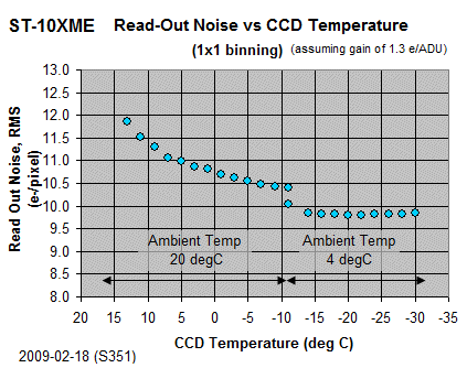
A separate run in which Read-Out Noise was calculated for 2x2 binning at a 29
different set-point temperatures indicated a mean read-out noise of 14.1
+/- 0.2 e-/pixel
The mean dark current value of the 60s dark frame was converted to a dark current per second by dividing it by the integration time
D ADU = μ(D-B) / 60 [ in ADU/pixel/sec ]
or in electrons
D electrons = g.μ(D-B) / 60 [ in e-/pixel/sec ]
The following results were obtained based on 3 tests.
| Binning |
Dark Current at -25deg C (ADU/pixel/sec) |
Dark Current at -25deg C (e-/pixel/sec) |
|||
| 1x1 | 0.15 | 0.43 | |||
| 2x2 | 0.70 | 1.85 | 4.3 times 1x1 (~4) | ||
| 3x3 | 1.64 | 4.25 | 9.9 times 1x1 (~9) |
The figure of 0.43 compares with an expected dark current of 0.06 e-/pixel/sec (based on expected 1 e-/pixel/sec at 0 degC and a 6 degC doubling rate temperature). Notionally it would seem that the camera is underperforming in terms of dark current
A further sets of tests were carried out to understand the behavior
of the
camera under various states of cooling.
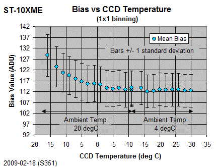
Bias/Dark Testing (2009-02-18)
Using an automated routine sets of 2 bias and 2 dark frames were acquired at
1x1, 2x2 and 3x3 binning over a range of set point temperature between 16 and
-30 deg C. The data was acquired in two batches: one indoors (ambient
temperature 20 deg C, where CCD was cooled through the range 16 to -11 degC )
and one outdoors (ambient temperature 4 deg C, where CCD was cooled
through the range -11 to -30 degC). Five minute stabilisation periods
were employed after each temperature
set-point change. Dark exposure times were 90s (1x1), 90s (2x2) and
60s (3x3) respectively.
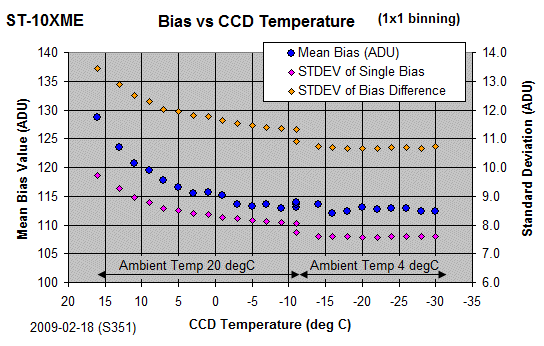
Bias
The Bias value for each temperature set point was recorded and
plotted.
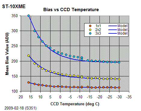
Whilst there is a degree of fluctuation (related to instability in CCD temperature and Camera Body Temperature ?) there is reasonable match up between the data sets collected at ambient temperatures of 20 deg C and 4 deg C. The data show that mean bias decreases with decreasing CCD temperature, with bias values that tend towards an almost constant value below around -20 degC. (Each point is the average of the mean from 2 bias frames).
|
Graphs of Bias vs CCD temperature (S351 Tests) |
 |
|
|
Bias values for 2x2 and 3x3 binned frames are incrementally higher than for 1x1 binned frames, but show similar trends of decreasing mean bias with decreasing CCD temperature. The data can be reasonably well modelled assuming a 'baseline' minimum with a doubling rate value of around 6.5 deg C
|
Graphs of Bias vs CCD temperature (S351 Tests) |
||||||||||||||||||||||||||||||||||||||||||||||||||||||
|
|
||||||||||||||||||||||||||||||||||||||||||||||||||||||
|
|
||||||||||||||||||||||||||||||||||||||||||||||||||||||
|
Modelled Bias Curves |
||||||||||||||||||||||||||||||||||||||||||||||||||||||
|
||||||||||||||||||||||||||||||||||||||||||||||||||||||
Mean Bias (at temperature T) = Bo + (Bref-Bo)/2^((Tref-T)/X) |
Besides understanding the performance of the camera under different operating conditions the principle purpose of generating functions that model the mean bias values is to use them in my observatory software to subtract estimated mean bias and dark values from raw light frames in order to provide realtime measure of sky brightness (in ADU/sq arc sec).
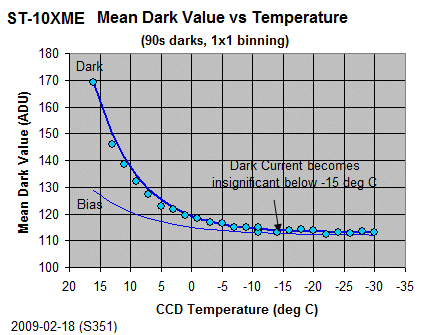
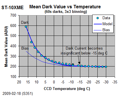
Dark Current
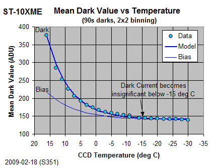
The Mean Dark value for each temperature set point was recorded and plotted.
Whilst again there is a degree of fluctuation (related to instability in CCD temperature and Camera Body Temperature ?) there is reasonable match up between the data sets collected at ambient temperatures of 20 deg C and 4 deg C. The data show that mean dark value decrease rapidly with decreasing CCD temperature, with dark values that tend towards the mean bias value at temperatures below around -15 degC. This indicates that dark current is exceedingly small (and practicallyt insignificant) at the CCD temperatures that will be normally be used for observing (typically -25 degC).
|
Graphs of Dark Values vs CCD temperature (S351 Tests) |
 |
|
|
 |
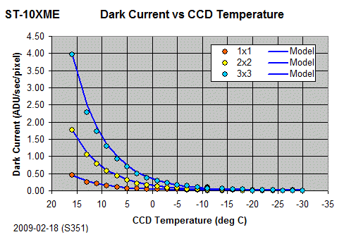
Subtracting Bias values from Dark values for each temperature
set point and dividing by the Dark Exposure time gives Dark Current values in
ADU/sec/pixel.
This confirm that the Dark Current of the ST-10XME is exceedingly low and become
almost zero below around -15 deg C.
At -25 deg C the Dark Current is 0.01 ADU/sec/pixel (1x1
binned darks) [ or 0.015ADU/sec/pixel (2x2), 0.02 ADU/sec/pixel
(3x3) ].
With gain of 1.32 e-/ADU the dark current of 0.013 e-/sec/pixel is significantly
lower than suggested by the camera specification - a welcome surprise but
consistent with measurements made on the KAF
3200ME CCD by Richard Berry in a different
brand of camera. [ reference here ]
|
Graphs of Dark Current vs CCD temperature (S351 Tests) |
 |
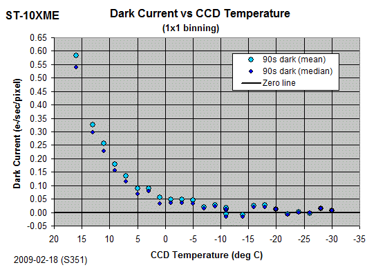
The dark current becomes so low that its level falls to much less that the read-out noise, such that dark current measurements made on individual frames are sometimes negative. (i.e. the uncertainty level associated with the read-out noise and very small dark values are such that the mean pixel value of a 90s dark exposure can sometimes be less than the mean pixel value of a bias frame taken immediately before or after the dark).
|
Graphs of Dark Current vs CCD temperature (S351 Tests) |
|
|
 |
For each temperature step the read-out noise was calculated from the standard deviation of the difference between pairs of bias frames and using a gain of 2.69 e-/ADU. Average readout noise for the 29 steps was 14.1 +/- 0.2 e-/pixel. A graph of read-out noise vs CCD temperature is shown below. As can be seen the data suggests that readout noise is pretty independent of temperature . However the mean bias itself is dependant on temperature and seems associated with dark current in the camera electronics as the bias frame is being read and counted.
|
Graphs of Mean Bias and Readout Noise vs CCD temperature (S324) |
 |
|
|
|
|
|
|
|
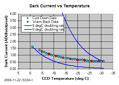
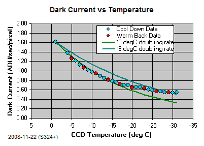
Graphs of Mean Dark Current vs CCD temperature (1x1 binning) |
|
Graphs of Mean Flat value vs
Exposure showing linearity up to ~
50,000 ADU for 1x1 binning, (66,000 e-) |
 |
 |
 |
|
Linearity/Well Capacity Testing |
 |
| Single Bias Frame (3x3 binning) |
 |
| Bias Frame 3x3 binning, 2009-02-18 |
| Hot Pixels (3x3 binning) |
| Bias Frame 17 x 60s (Average median), 3x3 binning, 2009-02-18 |
|
Graphs of Mean Dark Current vs CCD temperature (1x1 binning) |
|
|
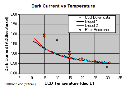
Graphs of Dark Current vs CCD temperature with simple model curves (S324) |
||
 |
 |
|
|
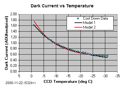
Graphs of Dark Current vs CCD temperature with best fitting models (S324) |
||
 |
 |
|
|
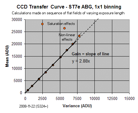
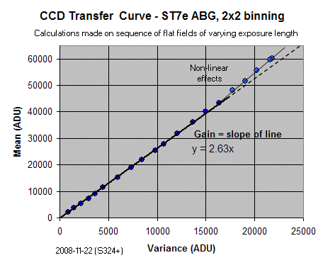
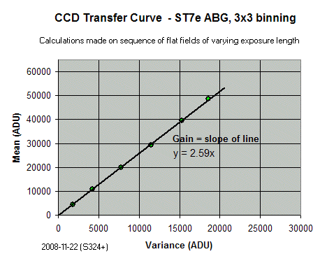
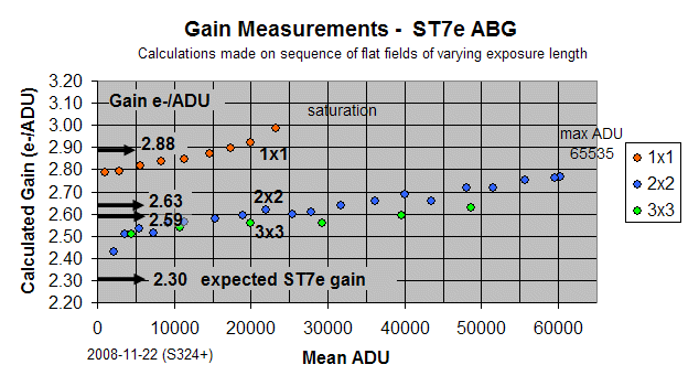
Gain Measurements / CCD
Transfer Curves (S324) |
 |
 |
 |
 |
|
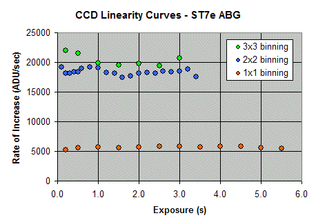
Linearity Tests (S324) |
 |
Back to Top
In early 2009 I purchased a Ted Agos Universal Adapter Tube fitted with an Antares focal reducer. This will become a main part of my new imaging setup from 2009 onwards.
|
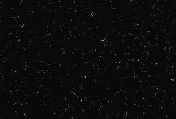
Cosmic Rays captured during acquisition of Dark Frames |
||
|
|
||
|
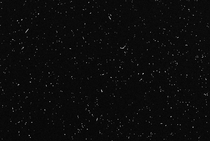
Cosmic Rays captured during 85 minutes |
||
|
Maximum of Dark Frame - Dark Median (50% size reduction) 17 x 300s, 3x3 binning 2009-02-20 (#352287-303) Full Size |
|
|
|
||
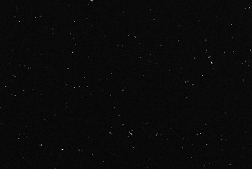
|
Cosmic Rays captured during 17 minutes |
||
|
Maximum of Dark Frame - Dark Median (50% size reduction) 17 x 60s, 3x3 binning 2009-02-20 (#352219-35) |
|
|
|
||
|
Cosmic Rays captured during 3 minutes |
||
|
Maximum of Dark Frame - Dark Median (50% size reduction) 17 x 10s, 3x3 binning 2009-02-20 (#352134-50) |
|
Back to Top
| This Web Page: | Notes - Session 351 (2009-02-27) |
| Last Updated : | 2015-05-16 |
| Site Owner : | David Richards |
| Home Page : | David's Astronomy Web Site |