David's Astronomy Pages
Notes - Session 609 (2018-01-03)
Notes
(S609)
Notes
Main
Home
Page
Notes
(S610.1)
David's Astronomy Pages
|
Notes (S609) |
Notes Main |
Home Page |
Notes (S610.1) |
| Session Aims & Highlights (Last Observing Session using Roll-Off Roof Observatory) | |
| - Night Summary Plot | |
| Operational Issues | |
| - Critical Issues (1), Major Issues (3), Minor Issues (6), Small Defects (2), Continuous Improvement (0) | |
| Condensation inside LX200 Telescope Tube | |
| Cloud Sensor - New Outside Location | |
| Sky Brightness Plot with Rain & Clarity data | |
|
|
Images from 2018-01-03 >> |
| 2018-01-07 | |
| ASCOM - Upgrade to 6.3 Platform | |
| LX200 Periodic Error | |
| Optec TCF-S Focuser - Upgrade to 6.0.6 | |
| Observatory Cabling (End 2017) | |
| 2018-04-27 | |
| LX200 RA Drive Examination | |
| LX200 RA Motor Unit Replacement | |
| LX200 Declination Gear Regreasing |
Main aims
Equipment & Software
Highlights
Notes
Summary Plots & Logs
|
Night Sky Summary Plot Top axis: Sky Brightness at Zenith (in ADU/s) Lefthand axis: Local Time (hh LT). Righthand axis: Sun Altitude (degs) |
||
| Top axis:
Sky Brightness at Zenith (in ADU/s) Cyan Curve: Measured Sky Brightness Yellow Curve: Model Sky Brightness Blue Curve/Points: Rain Green Line: Clarity Green Stripe Log: >6 Named Stars Lefthand axis: Local Time (hh LT) Righthand axis: Sun Altitude (degs) |
||
|---|---|---|
 |
Back to Top
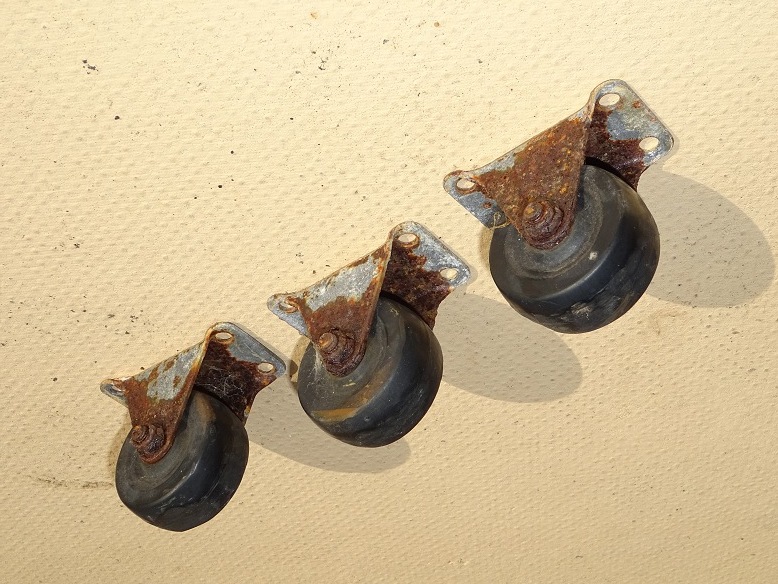
| 3 wheels found to have totally seized up (explains why roof had become so difficult to open/close) from demolishment of Old Roll-Off Roof Observatory (2018-03-25 to 2018-03-26) |
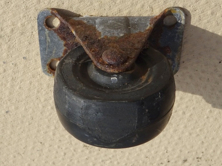
Seized Up Wheel - detail (Particularly severe abrasion on one of the seized wheels where it has rubbed along the top of the observatory wall) |
|
 |
 |
|
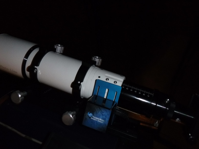
Motor Focus Unit and TS 80mm APO (device attached to back of scope is an Orion XY Finder) |
Motor Focus Unit and TS 80mm APO (night) | |
 |
 |
Back to Top/a>
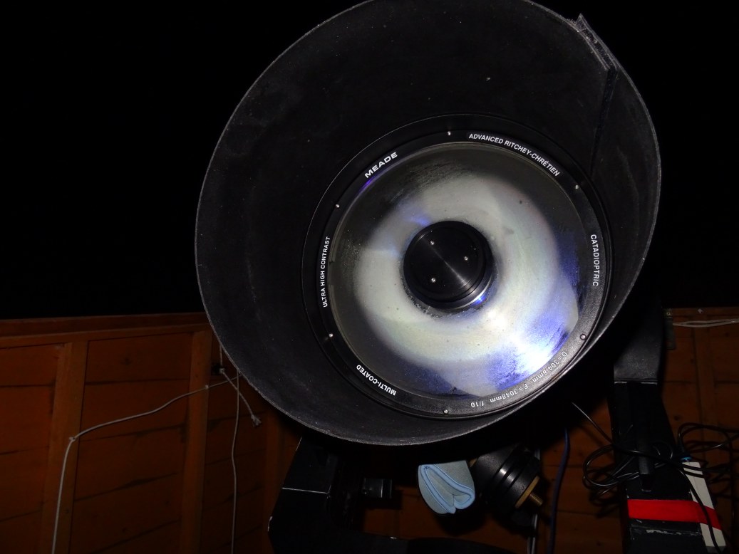
An image problem compromised many of the images acquired during session using LX200 + ST-10XME imaging train. This was same issue that affected the previous session. Investigations with a flashlight showed that there was condensation on the inside surface of the telescope's front corrector lens. Using a hairdryer on high heat seem to lift the condensation but some of it appeared to simply move onto the scope's main mirror.
| Condensation on inside surface of front correction lens (12" LX200R) Dew Heater is evidently working and is warming the outer ring of the lens but the heat is not enough to stop an inner ring of condensation from forming. High humidity in the observatory, a buildup of that humidity within the telescope tube, radiation of heat from the telescope optics into space and dropping of telescope surface below dew point are annoying factors. |
|
|
| 2018-01-03 |
Back to Top
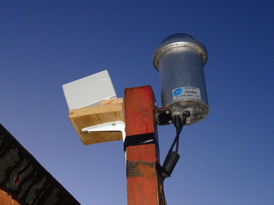
Cloud Sensor box (Aurora Eurotech) was moved from it's earlier position sitting inside the roll-off roof observatory (and only capable of monitoring the night sky when the observatory was open) to an outside position so that monitoring & recording of sky temperature/sky clarity and rain can be performed 24x7. The box was fitted to the same wooden pole used by the AllSky Camera, but positioned slightly lower to avoid it blocking the AllSky Camera's 180deg view, and tilted at around 10-20 deg to enable heavy water to drain off the ceramic rain detector as recommended by the Cloud Sensor user manual
| Cloud Sensor box in new Outside Position |
 |
| 2018-01-01 |
Back to Top
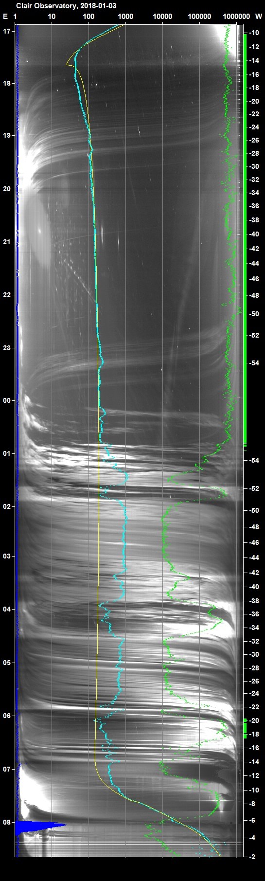
Night Summary Brightness Plots that previously displayed a sequence of E-W lines from AllSky Camera against time, stars indication (green stripe), modelled and actual sky brightness (yellow line and cyan line respectively) from AllSky Camera Image measurements have been just been updated to also show Clarity (Green line) and Rain (Dark Blue Line). This data come from the Aurora Eurotech Cloud Sensor (that has just been repositioned to a new outside location) which is now been collected on a 24x7 basis. The plot shows rain at 08:00 in the morning, but the graph points doesn't highlight this important environmental data sufficiently well. The graph will therefore be modified to show rain as a filled line plot.
| Sky Brightness Summary Top axis: Sky Brightness at Zenith (in ADU/s) Cyan Curve: Measured Sky Brightness Yellow Curve: Model Sky Brightness Blue Curve/Points: Rain Green Line: Clarity Green Stripe Log: >6 Named Stars Lefthand axis: Local Time (hh LT) Righthand axis: Sun Altitude (degs) |
||
|---|---|---|
|
|
Back to Top
ASCOM (standing for 'Astronomy Common Object Model') is a set of vendor-independent and language-independent interface standards for drivers that provide plug-and-play control of astronomical instruments and related devices.
ASCOM Plaform on the observatory main laptop was upgraded from Platform 6.2
to Platform 6.3 on 2018-01-07.
(
https://ascom-standards.org/Downloads/Index.htm ) .
ASCOM Platform Developer Components (For Platform 6.3) was also downloaded and installed, in case I have a need to create/build a driver or a middleware layer.
ASCOM .NET Client Toolkit from C# was also downloaded. This is Visual Studio C# project that shows how to use the ASCOM .NET Client Toolkit. This is a console application which contains code that access each type of driver, using the chooser and pre-selecting the simulator for each. The project was examined and run in Visual Studio 2017.
Back to Top
Following the possible damage to LX200's RA drive at the end of the last observing session on 2018-01-03/S609 (when the observatory roof hit the attached TS 80mm guidescope and forced the LX200 fork/tube to be rotated by some 15-20 degrees relative to the base and causing the RA drive to jump across the teeth with a loud clatter) and the corrective manual rotation of the scope, Periodic Error was assessed during a 5 hour maintainance session on the evening of 2018-01-07.
As a result of this data the main RA gear was later examined for physical signs of damage and then following on from this it was decided to replace the RA motor unit (2018-04-27)
|
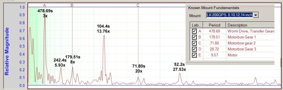
Periodic Error Asssement / RA Tracking (2018-01-07) (whilst the overall peak-to-peak error is not excessive, the dataset is heavily overprinted by RA jumps occuring at a frequency of 104s. These don't overlay from one cycle to another and therefore can't be removed by standard Periodic Error Correction (PEC). Furthermore they degrade periodic error information that might be occuring on known mount and other integer fundamentals. |
|
|
|
Frequency Spectrum Plot of the above data Apart from the main 8 minute cycle, the dataset is dominated by RA jumps occuring at a frequency of 104s which can't be removed by standard PEC |
 |
|
Periodic Error measurement from one particular section of the
main RA gear (large RA displacements every 8 minuties indicate the potential damage to some of the main teeth) |
|
|
|
Periodic Error measurement from a different part of the main
RA gear (large RA displacements over some sections of the main RA drive, but disappearing on adjacent sections) |
|
|
Back to Top
Recent sessions have encountered intermittent problems with the digital
connection to Optec -TCF-S focuser, whereby the connection to focuser/handbox
made via CCDSoft Camera.Connect would commence ok (controlled by CCDApp2) and
would allow position/temperature reading and focus changes in response to set
focuser steps commands from CCDSoft.Camera (again controlled by CCDApp2), but at
some point in the session the connection would be lost for no clear reason.
Sometimes the lost connection could reestablished or seemingly restart by
itself, othertimes it couldn't.
After losing conection during
maintainance session on 2018-01-07, attempts to connect to the TCF-S
focuser from Optec's TCF-S Focuser application failed with the message that the
serial connection was in use by another program. This message was given with and
without CCDSoft/CCDApp2 programs running.
In an attempt to resolve this issue, the currently installed Optec TCF-S
driver (5.4.2, 64 bit, released 2013/10/26) was removed, and the latest driver
(6.0.6, any CPU, released 2017/12/06) was downloaded and installed in its place.
(
https://optecinc.com/astronomy/downloads/tcf-s.htm )
Connection and operation to TCF-S Focuser was checked using both CCDSoft and
Optec's own TCF-S Commander application.
[After installing I read the
message on Optec website saying "You MUST install these drivers in
administrator mode. Download and unzip the file to a temporary location, open
the folder and right-click the Setup.exe program. Select "Run as Administrator"
to avoid a Windows Error:1001 message. This driver is digitally signed by Optec,
Inc." Although I didn't encounter a problem when operatin TCF-S
focuser from TCF-S Commander or from CCDSoft/CCDApp2 I was concerned that there
might be a problem with ASCOM driver ot being properly registered , so I
uninstalled and then re-installed the Optec TCF-S driver (using 'Run as
Administrator' on the second occasion).
Back to Top
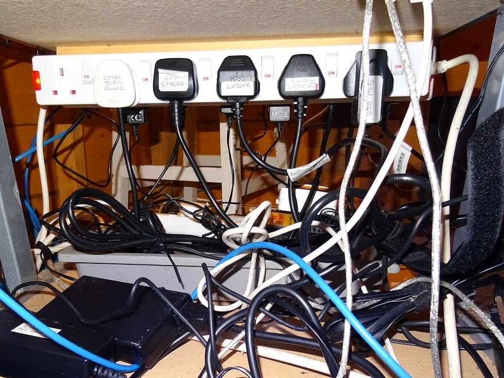
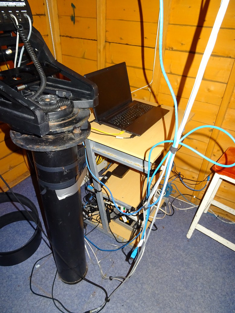
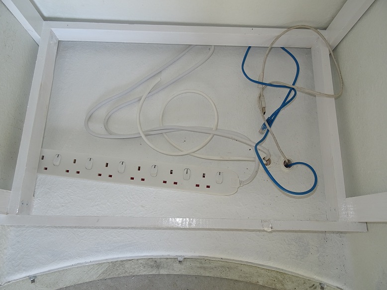
TThe Clair Observatory uses a large number of cables for serving the various
pieces of equipment (high voltage power leads, adapter, low voltage power leads,
ethernet cables, USB cables, serial cables & special cables (combined power &
data). In my current roll-off roof observatory all these cables come together as
a cable nest beneath the observatory's desk where the Main Observatory Laptop
and AllSky&Weather Laptop are situated. Whilst the situation at the back
of the desk is a bit of a cabling-from-hell mess, the situation is partially
mitigated by coiling/tryig up unused lengths of cable and labelling plugs,
adapters and cables. Some pictures of the current state of cabling is shown
below.
Note: It is anticipated that cabling can be better organised/arranged
in the new dome observatory planned for 2018. This will in part be accomplished
by using one observatory
bay for AllSky-Weather Monitoring and another bay for the Main Observatory Computer with
Telescope/Camera Control.
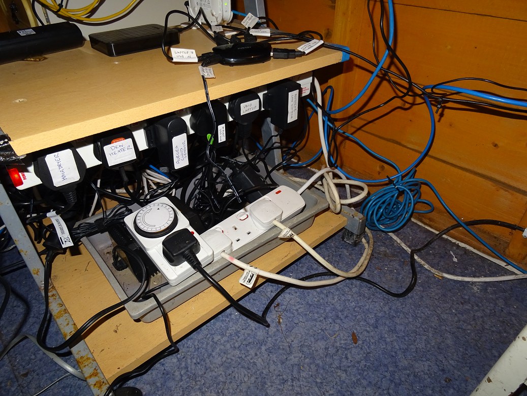
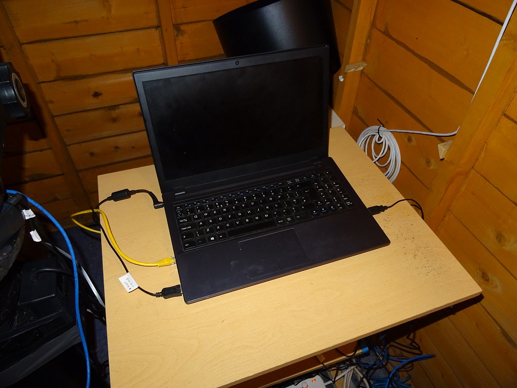
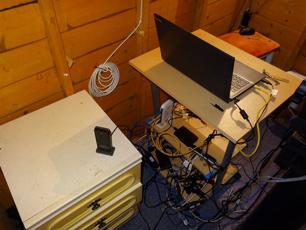
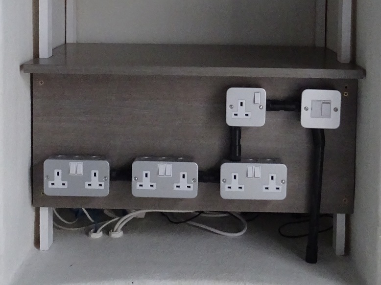
| Desk Front (lower half)br>AllSky USB Hub on middle shelf Power Strips & Power Adapters on lower shelf |
Desk Top Main Laptop on Desk Top is only present when an observing session is in progress. An always-on AllSky-Weather Laptop (not visible) sits below on a pull-out 'keyboard shelf' |
|
 |
 |
|
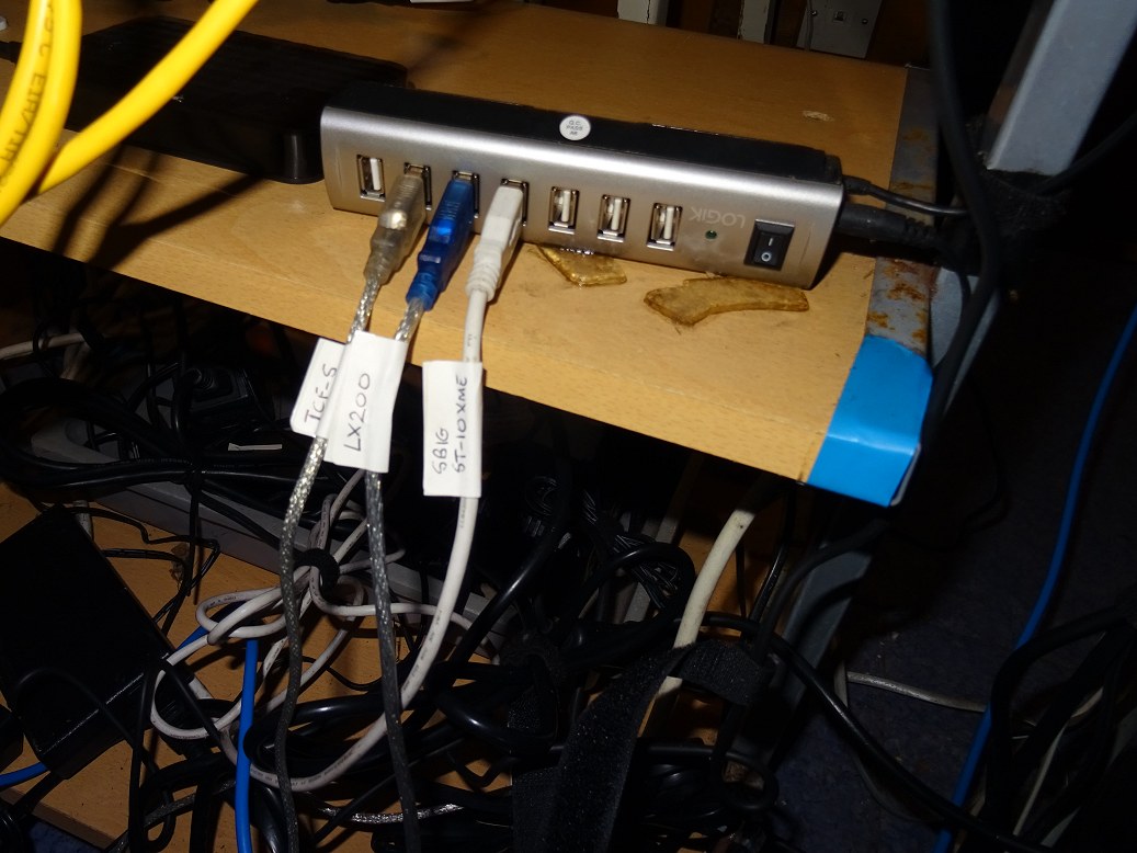
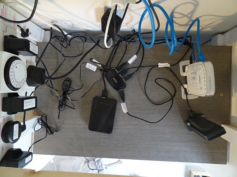
| Main USB Hub on middle shelf Comms to LX200 telescope, TCF-S focuser & ST-10XME camera |
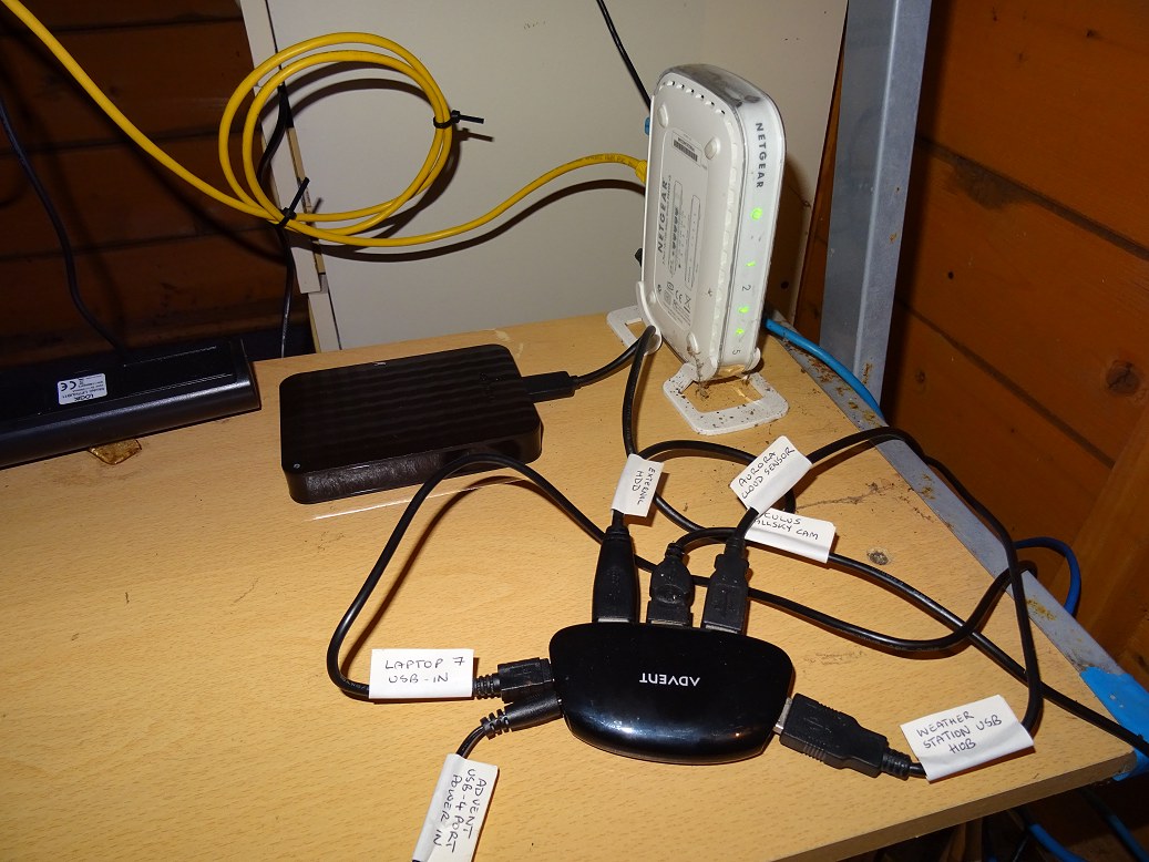
Ethernet Router & AllSky USB Hub on middle shelf Comms to Oculus AllSky Camera, Cloud Sensor, Weather Station USB Hub Communicator & External USB Drive |
|
 |
 |
|
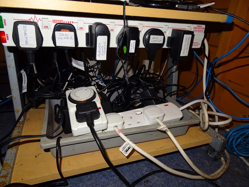
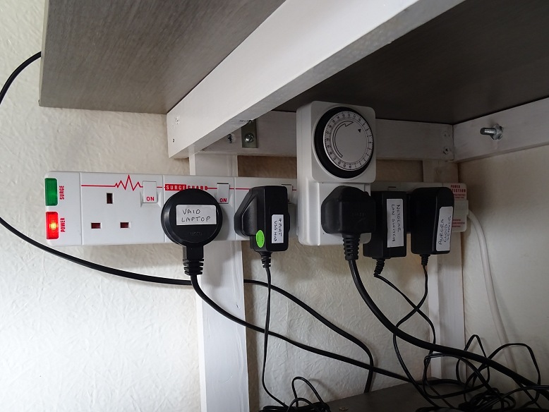
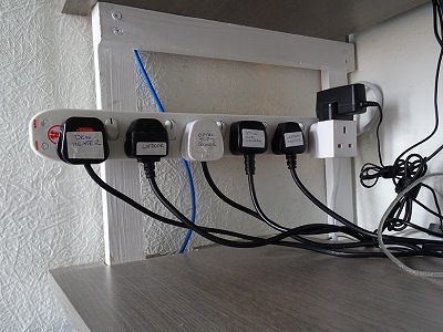
| Front Power Strip & Extra Power Strip Power supply for AllSky Laptop + Connected Equipment (also supplies Dew Heater / Hairdryer) |
Rear Power Strip Power supply for Main Laptop + Connected Equipment (LX200, ST-10XME Camera, TCF-S Focuser, USB Hub) |
|
 |
 |
|
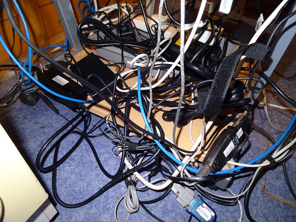
| Nest of Cables on lower shelf / spilling onto floor Power Cables & Data Cables (USB, Serial, Ethernet) |
Observatory Desk & Power/Data Hub (right) + USB Hub Communicator to Weather Station (fixed on cabinet in foreground, left) |
|
 |
 |
|
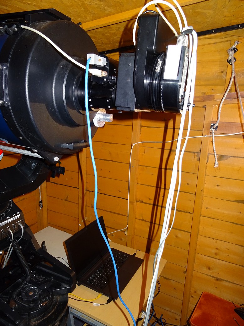
| Cables at back of LX200 Telescope & Camera | Cables to / from LX200 Telescope & Cameras | |
 |
 & & |
Update: 2018-04-29
The improvement in cabling
situation in the new Dome Observatory is shown by the pictures below:
Back to Top
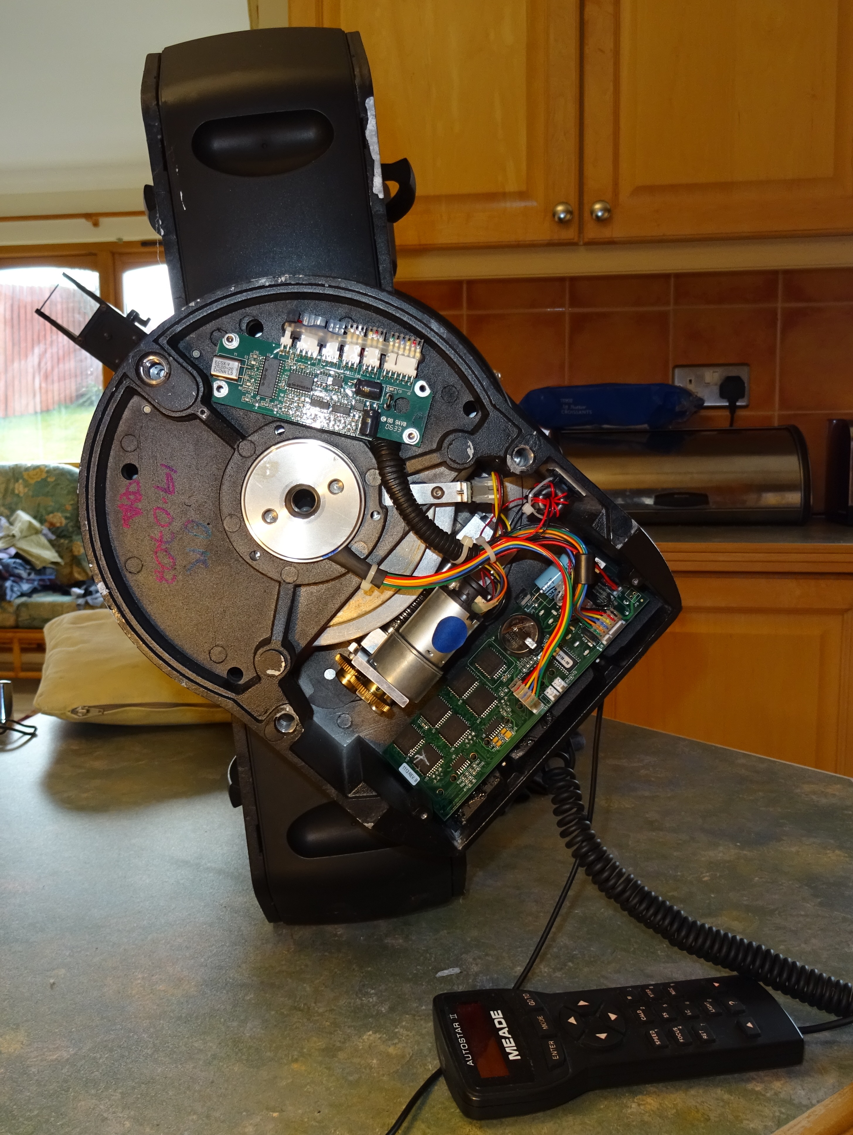
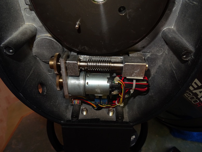
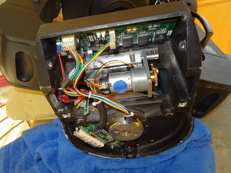
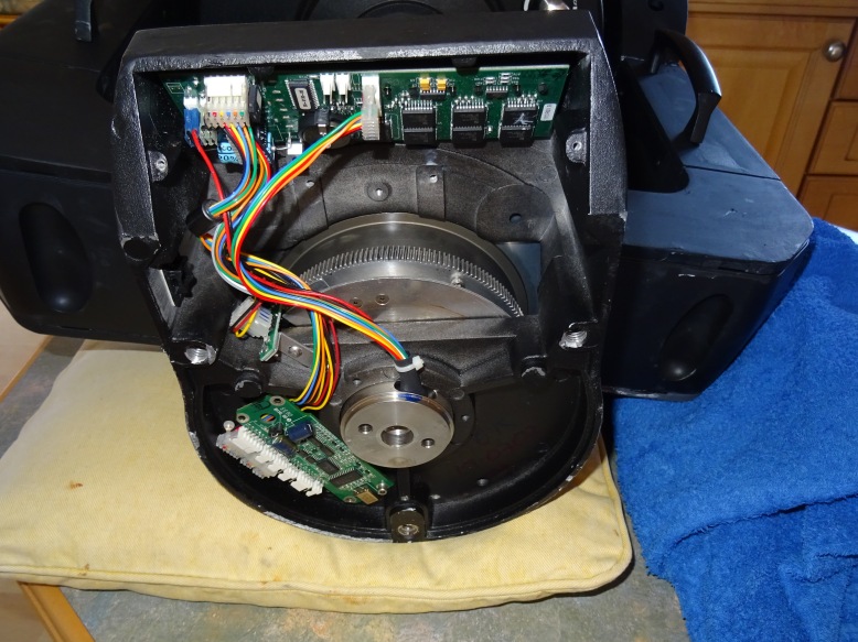
With my 12" LX200GPS/R removed from my old roll-off roof observatory whilst a new dome observatory is being built (April 2018), and in anticipation that the scope will require a potential major repair to its RA gears due to poor RA tracking performance (PE Measurements 2016-12-22 to 2016-12-27 & measurements 2018-01-07) and potential damage (incident report 2018-01-03) the bottom plate of the scope was taken off and the RA Drive examined. This was done with the scope powered up so that I was able to watch and listen to things whilst turning it through a full 360 degrees so that I can see the entire circumference of the main drive.
The examination showed the following:
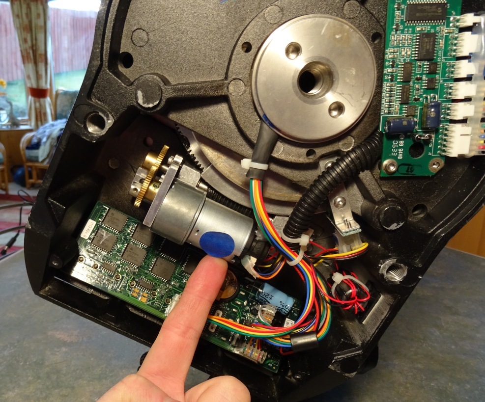
- RA motor/gearbox sounds ok when it is running, just
a normal whirling sound as it ticks over (pictures)
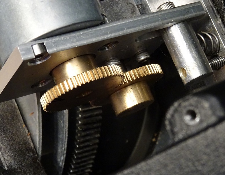
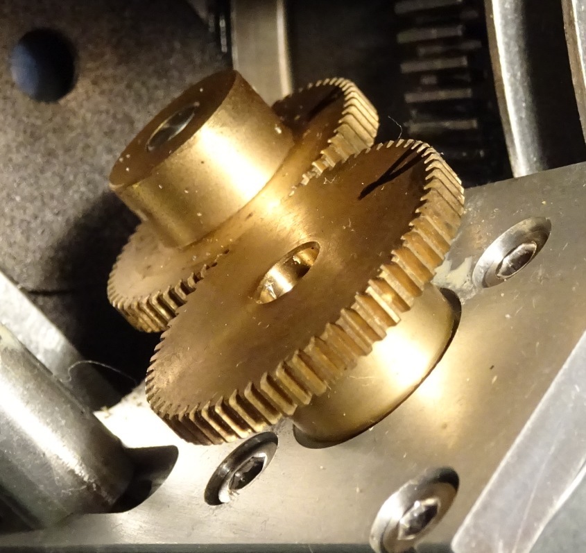
- Brass Transfer gears look ok, all teeth intact and no
obvious damage or major wear. The tips of one of two might have been a shade
narrower than the rest, but nothing suspicious. (pictures
of transfer gears)
- There is
some in/out movement (play) in the axle coming out of the gearbox assembly which
holds the first transfer gear. It amounts to about 15-25% of the thickness of
the transfer gear and may be entirely normal. Generally there is 100% overlap
between the two transfer gears, but depending on how the base was lying there
could be only 75% overlap in some positions. Doesn’t seem to be a problem. I had
the base vertically positioned in the bench which is obviously not the
orientation it has when mounted on the wedge.
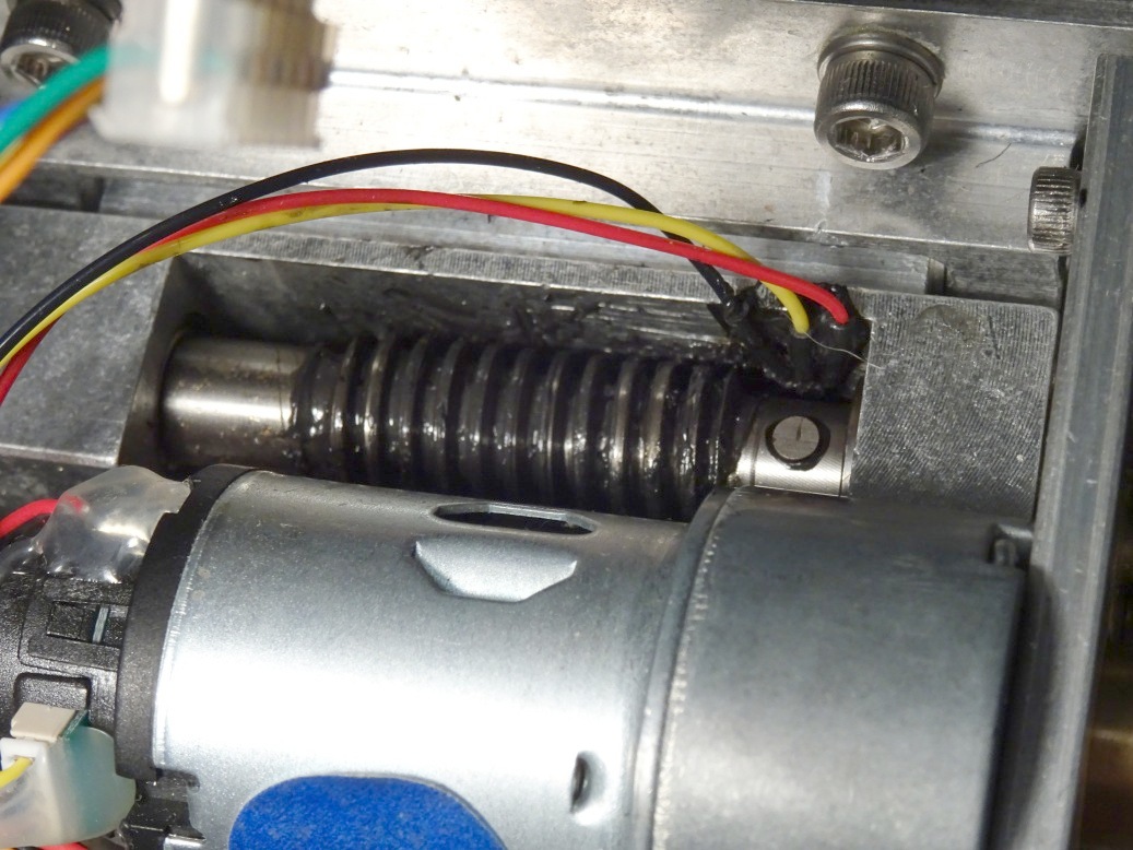
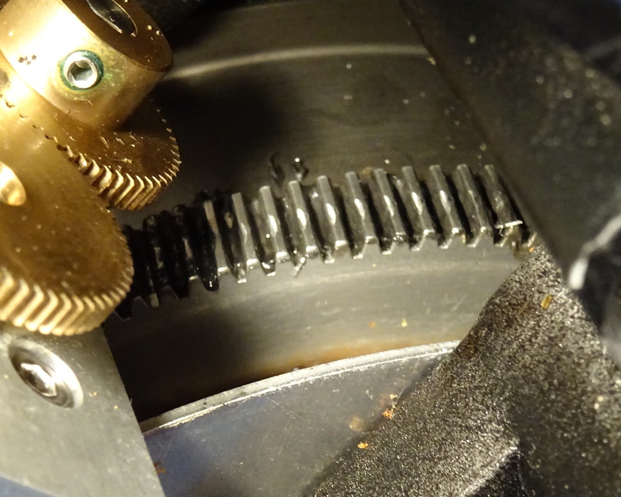
- Wormgear surface was a bit difficult to see fully with
the black grease , but there was no obvious damage to the worm drive teeth from
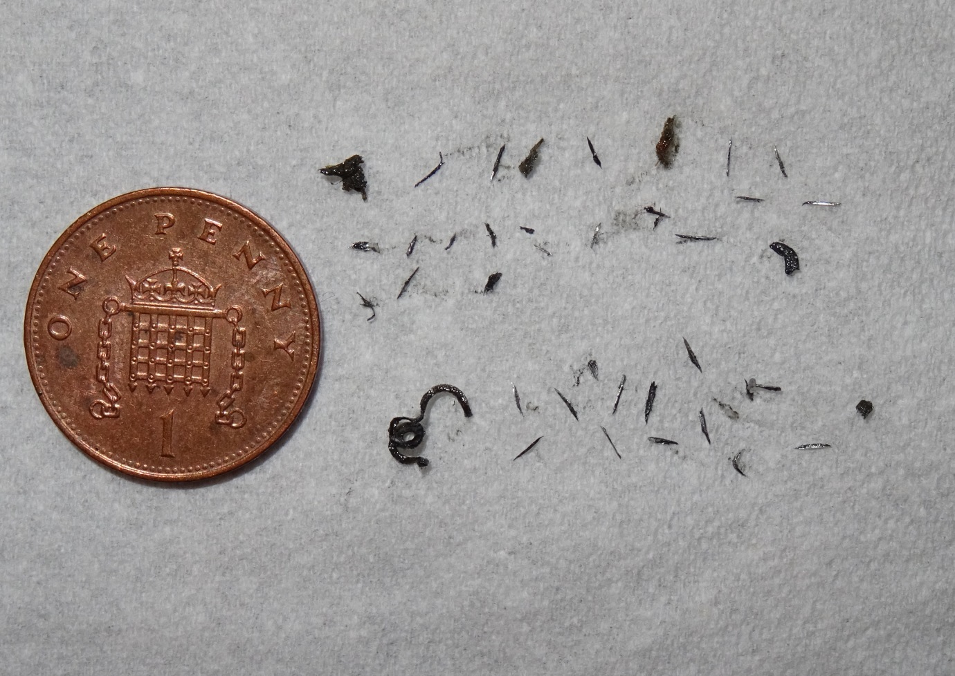
what I could see (pictures of wormgear). There
was however quite a few splinters of metal up to 2-3mm in length, caught up in
the grease, plus a spiral sward of metal which could be 8-10mm long if it were
straightened (picture of the metal pieces
). I don’t recall noticing any bits of metal when I opened the scope for Tension
Spring tightening in Dec 2016, but I wasn’t looking so hard then. So can’t tell
if the metal relates to a specific incident of recent damage or it reflects 9
years of normal usage.
Regardless of the impact of the metal missing from where it should be, the
presence of bit of metal would I imagine lead to a certain amount of random RA
deviations as a piece gets run-over in the gears every so often.
- The leading and trailing ends of the spiral worm are
particularly thin. I expect it’s designed and manufactured this way, but with
the evidence of metal sward I couldn’t rule out that it could have come from
this place. However these thins ends don’t appear to touch the main RA drive in
anyway so I can’t really see how there could have become thinned by RA
movements.
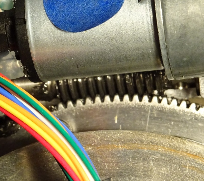
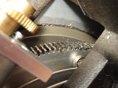
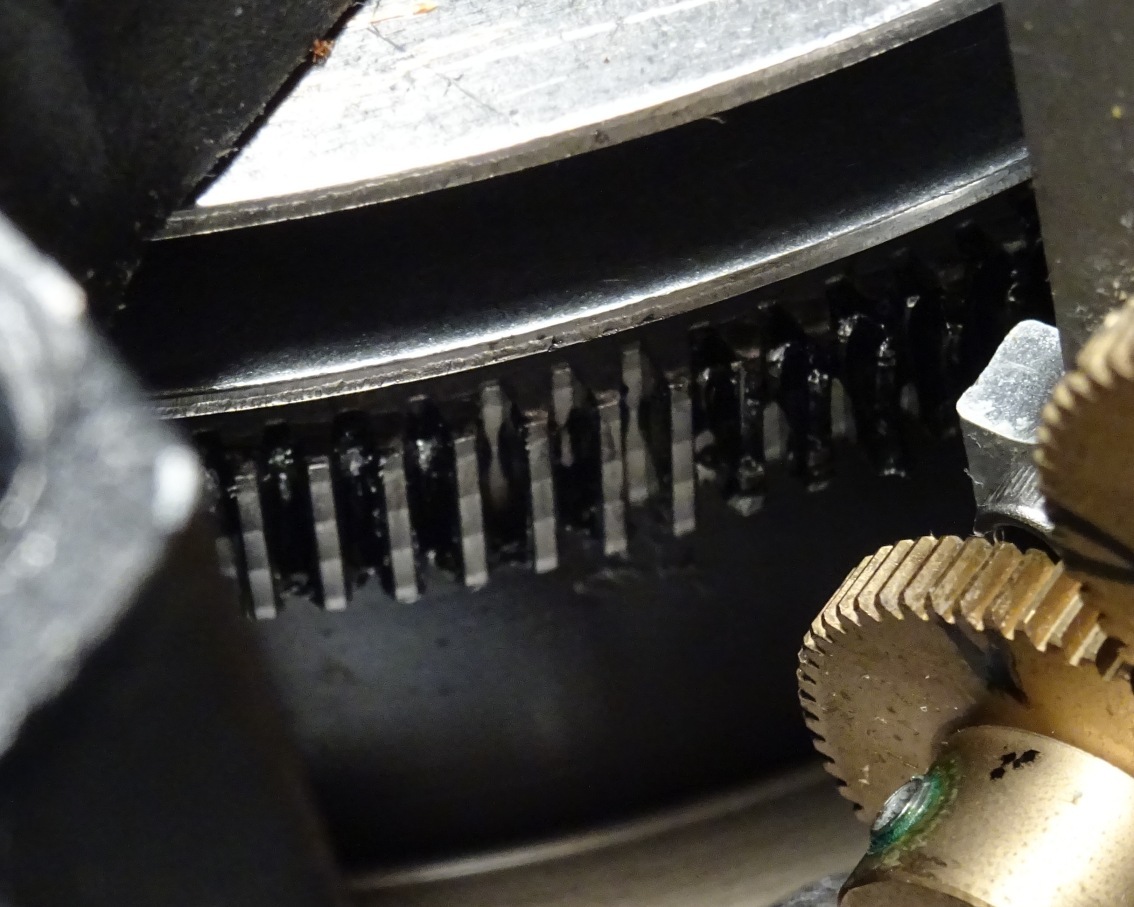
- The main RA drive
was intact with no missing teeth or obvious excessive damage. Again mixed in
with the grease on the main RA drive were small splinters of metal. There was
wear pattern on the tips (pictures of Main Gear
surfaces) of the 180 teeth. It’s not clear how much of this is wear and tear
and how much is due to the RA drive jumping across the worm drive. By wiping the
grease from different parts of the circumference it evident that the wear
pattern on the teeth tip (tops) were consistent between adjacent teeth but would
vary around the circumference. Some sections looked in pretty good shape, whilst
others had a single central ‘divot’ or scrape. I couldn’t see any signs of
damage on the sides of the teeth where they were visible (the grease doesn’t
give me a complete picture. I’m imagine that imperfections on the sides of the
teeth which are in touch with the worm gear are more important that the tops of
the teeth. I might be wrong?
-
When slewing (with the base rotating round, rather than the scope itself which
was stationary on the table) the RA produced uncomfortable sounds (sort of a
chatter) in the positions where gravity pulled the worm block away from the main
RA drive. Pushing the motor/worm block towards the RA drive would restore normal
sounds. The base is vertical in these test which might be more extreme result
than it would be in its normal state when mounted on a wedge, but this was the
problem before tension spring tightening in Dec 2016.
Following conversation with Steve Collingwood from SC Telescopes it was decided that the best solution to move forward with was a a total clean/regreasing of the main RA gear and a self-replacement of the RA Motor Unit (£185, with postage). I made these repairs a few weeks later (2018-04-27) after recieving the new RA Motor Unit and my observatory project being ready to install the telescope
| LX200 RA Gear
Examination (2018-03-29) |
||
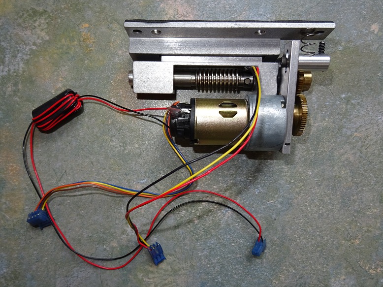
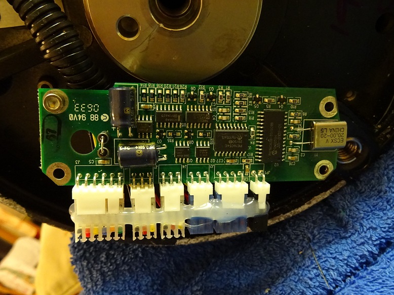
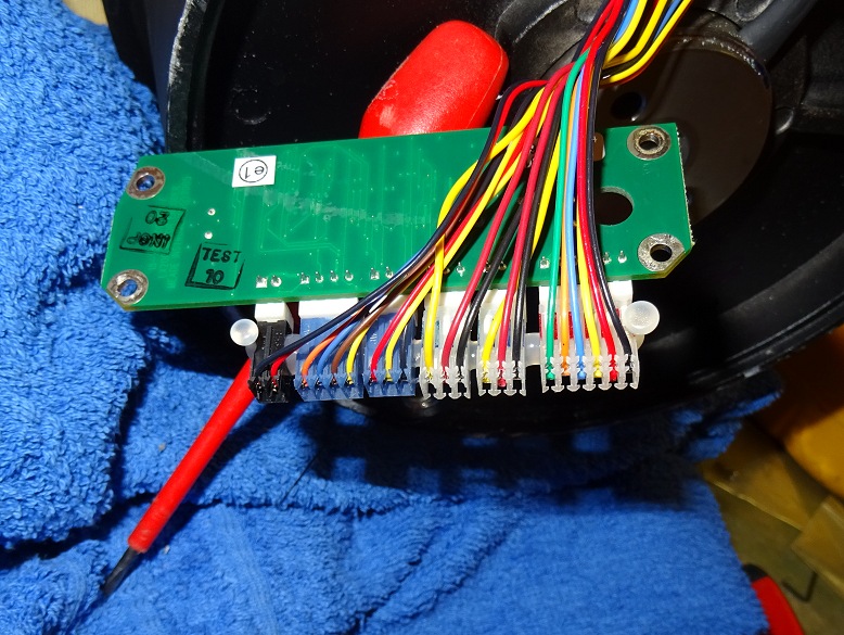
| RA Gear Examination | RA Motor Unit | |
 |
 |
|
| Transfer Gears | Transfer Gears | |
 |
 |
|
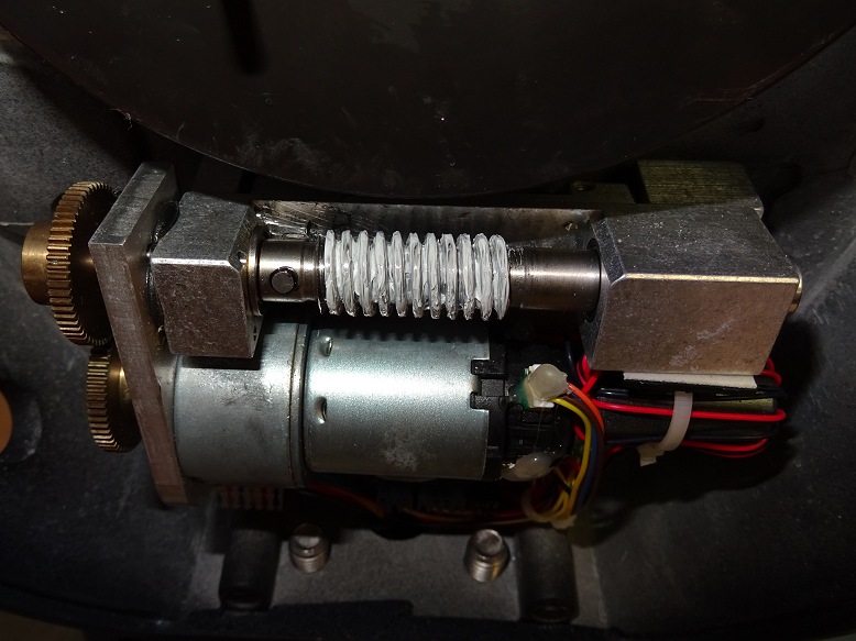
| Worm Gear | Worm Gear & Main Gear | |
 |
 |
|
| Metal Pieces extracted from
grease on worm-gear & main RA gear |
Old Grease on Main Gear (with embedded metal pieces) |
|
 |
 |
|
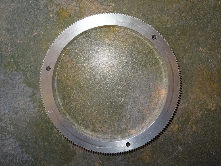
| Main RA Gear (normal surface) | Main RA Gear (damaged surface ) | |
 |
 |
|
Back to Top
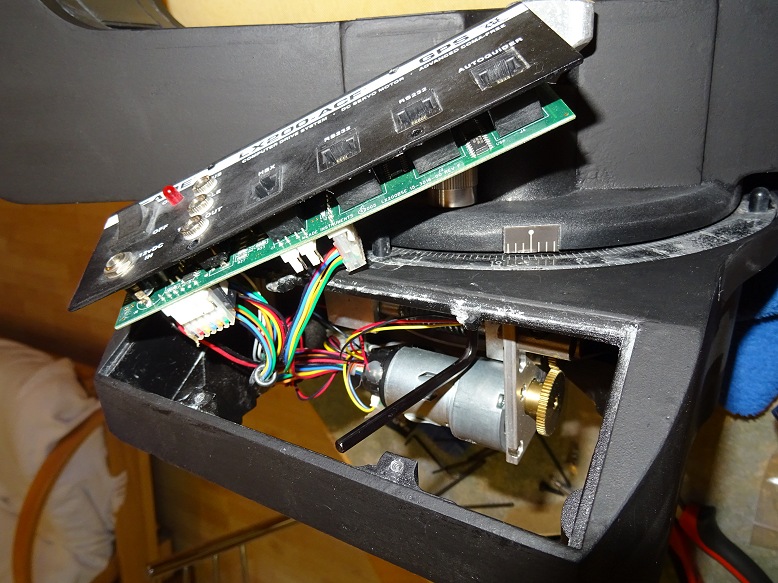
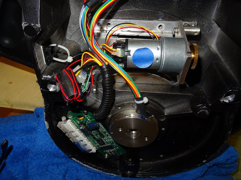
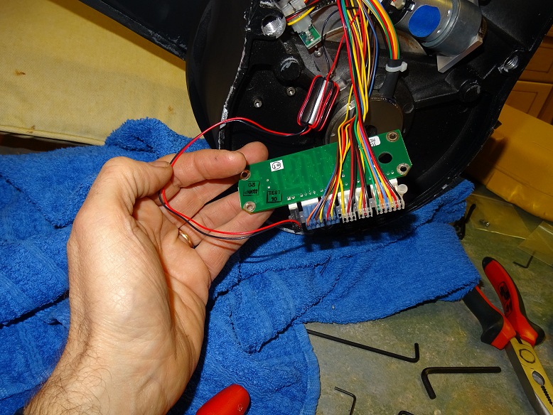
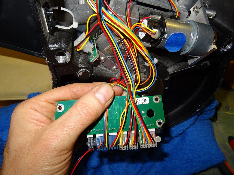
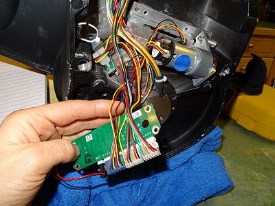
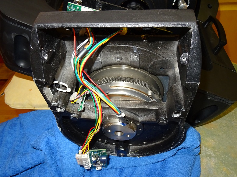
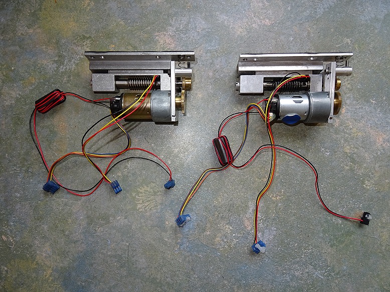
With my 12" LX200 removed from my old roll-off roof observatory whilst a new dome observatory is being built (April 2018), opportunity was taken to replace its RA motor unit in an attempt to solve RA tracking error problens that have been adversly affecting the performance of the scope over the past 18 months. (see RA Drive Diagnostics 2016-12-22 to 2016-12-27 & 2018-01-07
The new RA motor unit comprises new motor, transfer gears and wormgear, and cost £185 (including postage). The following pictures illustrate various steps during the motor unit replacement. Opportunity was also taken to regrease the Declination Drive
Back to Top
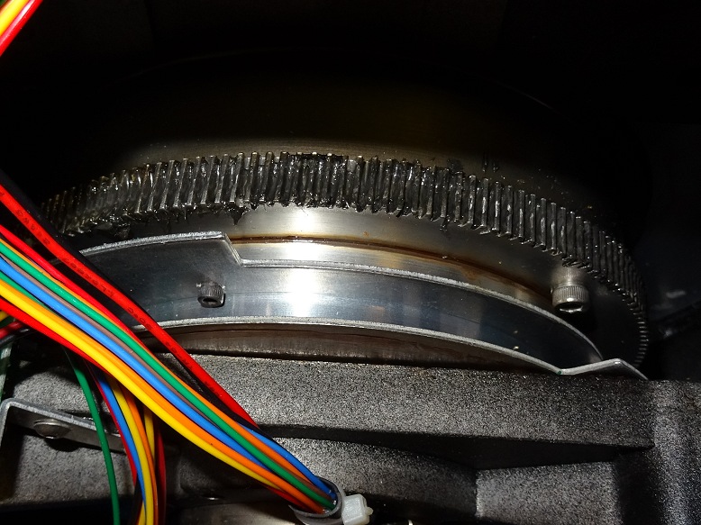
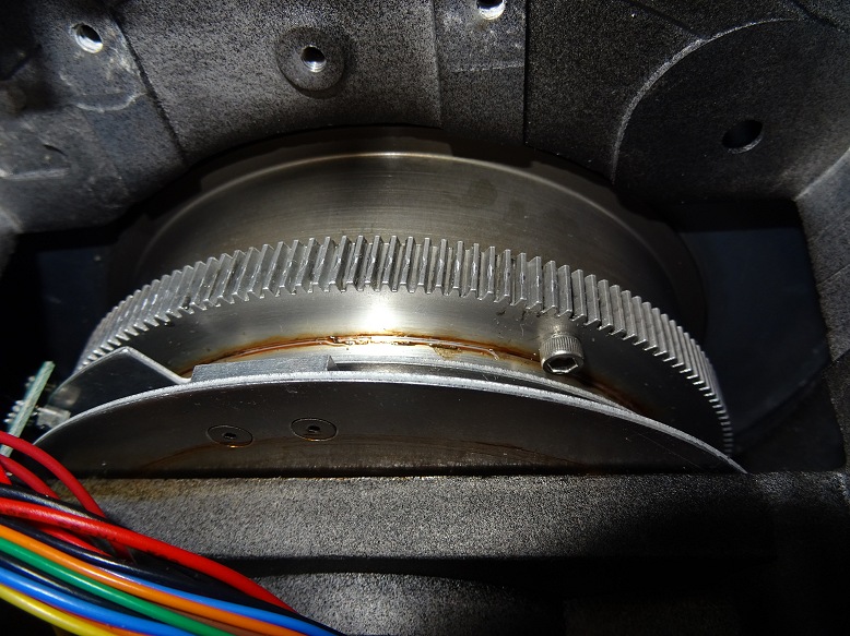
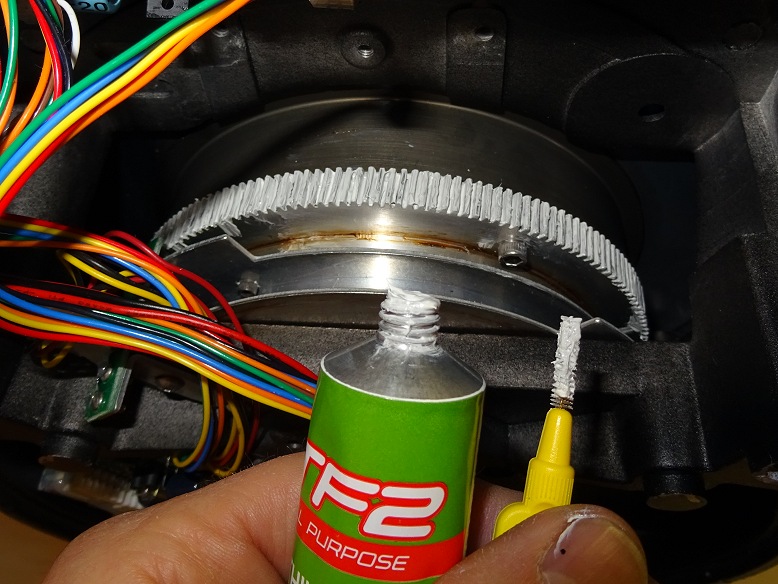
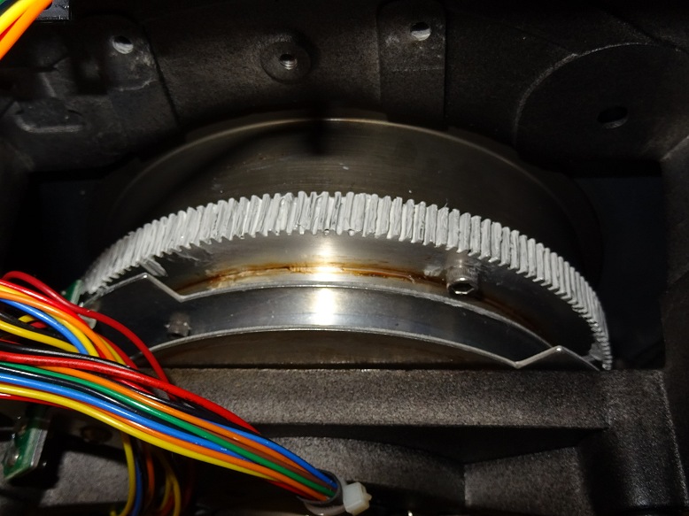
With my 12" LX200 indoors for a RA Motor Unit replacement (including cleaning and regreasing the Main RA drive) opportunity was taken to clean and regrease the Declination Drive at the same time. The re-greasing made an immediate improvement to the smoothness/sound of declination slewing.
| Declination Gear Regreasing (2018-04-27) |
||
| Dec Motor Unit (picture shows main Dec gear removed with the wormdrive exposed for cleaning) |
Main Dec Gear after cleaning (picture shows gear before re-greasing with Lithium Grease) |
|
 |
 |
|
| Dec wormdrive after cleaning | Dec wormdrive after re-greasing | |
|
|
 |
|
Back to Top
| This Web Page: | Notes - Session 609 (2018-01-03) |
| Last Updated : | 2024-02-20 |
| Site Owner : | David Richards |
| Home Page : | David's Astronomy Web Site |