David's Astronomy Pages
Notes - Session 611 (2018-05-17)
Notes
(S610)
Notes
Main
Home
Page
Notes
(S611.2)
David's Astronomy Pages
|
Notes (S610) |
Notes Main |
Home Page |
Notes (S611.2) |
Main Aims
This was a two part (daytime & nighttime) session to continue formal commissioning of the new Dome Observatory including :
Equipment & Software
Highlights
Notes
Summary Plots & Logs
|
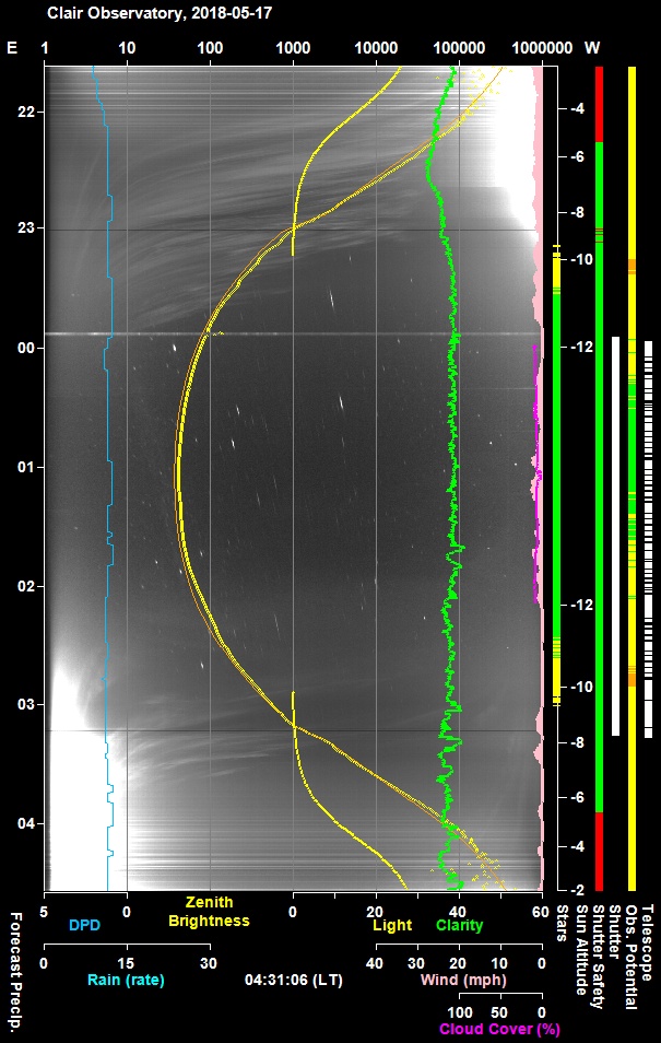
Night Sky Summary Plot -
2018-05-17 Top axis: Sky Brightness at Zenith (in ADU/s) Lefthand axis: Local Time (hh LT). Righthand axis: Sun Altitude (degs) |
 |
Back to Top
Fig 1. Pointing Discrepencies from Mapping Run
Back to Top
To ensure that there are no issues
during automated/unattended operation of the new observatory and that specifically
there would be no issues during an upcoming TPoint mapping run a slewing
safety check was undertaken during daylight hours.
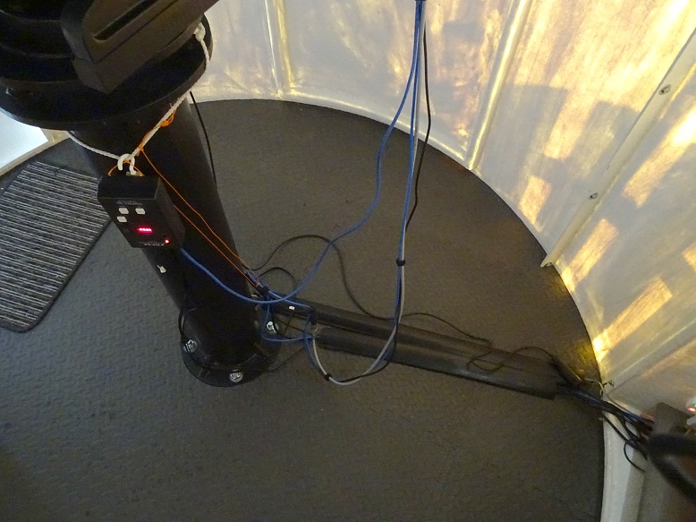
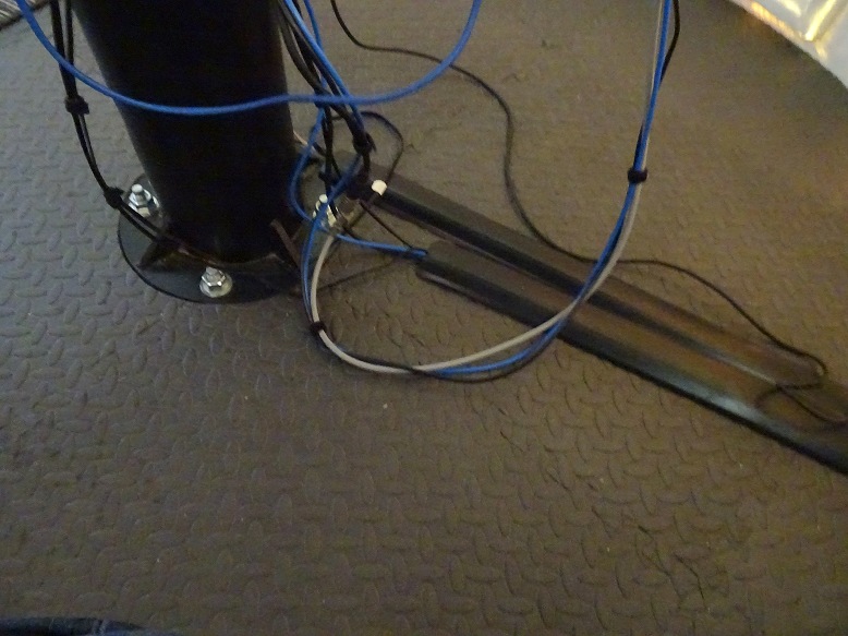
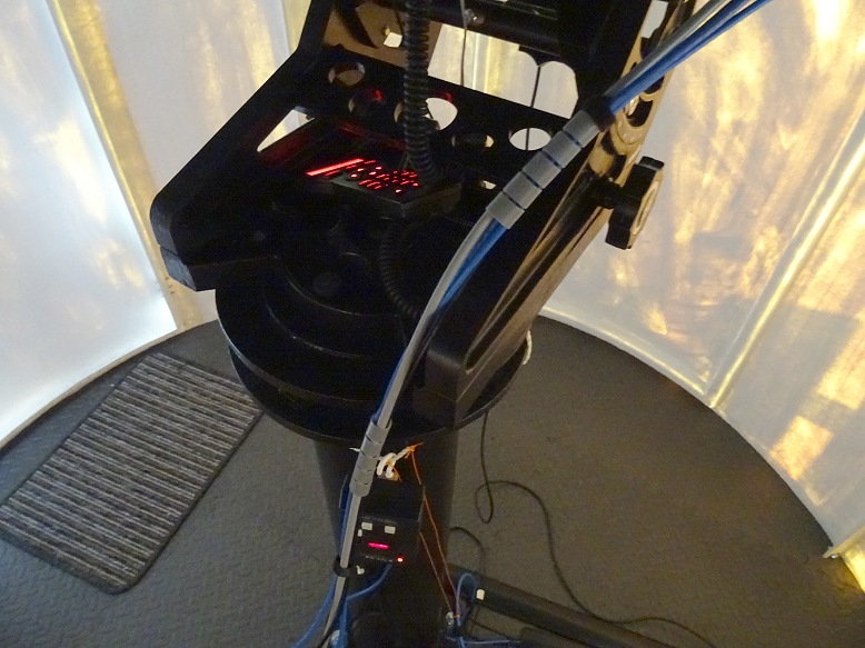
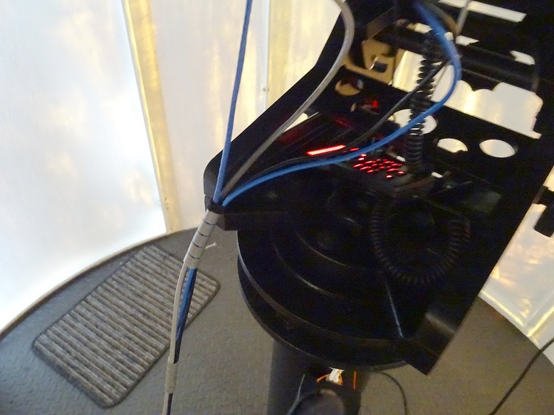
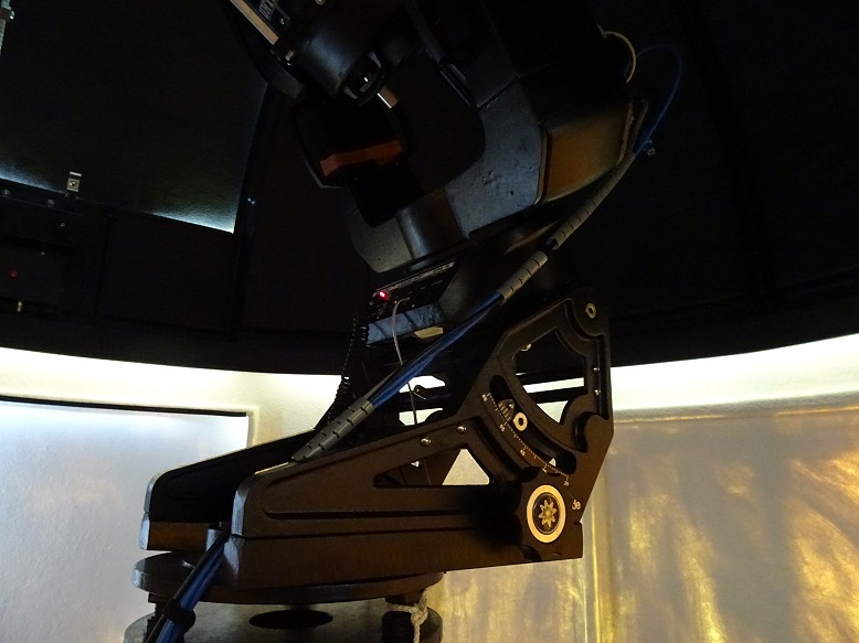
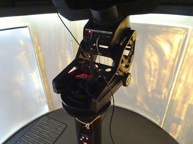
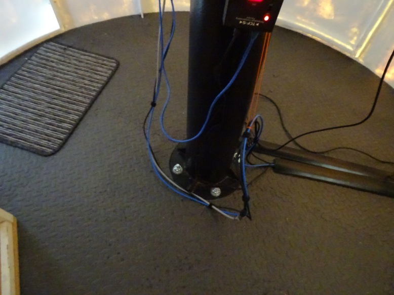
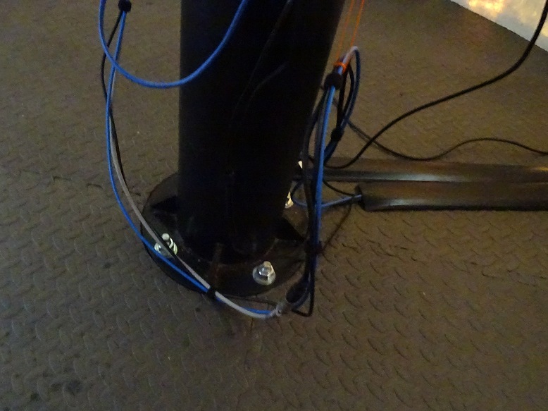
The telescope was
slewed between different TPoint Mapping Points distributed across the sky, and
the cables attached to the telescope and camera were carefully watched to ensure
that the cables moved relatively smoothly and didn't catch or hold up on the
pier, wedge or telescope forks. Checks were made to ensure that
camera cleared the base of the telescope at all azimuth positions, up to a set
(safe) declination limit. Checks were also made that slews just east or just
west of north slewed the scope the long way around, unwinding the cabling in the
process rather than take a short cut across the north line.
The slewing safety check was performed with Dew Shield in place in order to check and confirm that the dew shield cleared all Dome Roof flanges. The safety check was performed with the Dome closed and not slaved to the telescope in order to ensure that the telescope optics weren't exposed to the sun and to speed up the checking process.
As a result of the test additional bundling of the cables going to the camera was performed to ease its passage over the sides of the wedge base. The test showed that whilst the recently introduced string to hold the camera/focusser cables off the floor worked when pointing at low altitude, it didn't prevent cables from dragging on the floor when pointing at high altitude. This does not impede the slewing or movement of the scope and is therefore not a safety concern, however cable dragging might compromise image quality. This will be monitored and if a factor the cabling will be reviewed again.
Back to Top
Initial test exposures showed that the focus on the LX200 scope had drifted
since the last two commissioning sessions. This was probably due to the warmer
conditions during this session. Scope was refocused using USB-connected
TCF-S focuser and using the focusing routine incoporated into my
Observatory Control program (CCDApp2). This measures the FWHM of a star at
a series of different focus offsets from the current focus position, before
determing a best fit curve through the data and then automatically moving TCF-S focuser to the
peak focus position. FWHM (Full Width at Half Maximum) at peak focus was
measured at around 2.0 arc secs which is pretty good for the site.
As
there have been no changes to the optical train or filter wheel the existing
'set of Focus Offsets for different filters' will used for the time being. The
existing Temperature Compensation Equation will also be used, but it could
benefit from reevaluating using data collected in the new Dome Observatory.
|
Focusing Profile 1 |
||
 |
||
|
Focusing Profile 2 |
||
 |
||
Back to Top
Whilst Polar Alignment was estimated to be correct to within 1.5 arc minutes based on PemPro's Polar Alignment Wizard (see graphs), Dec & RA star drift seen whilst measuring periodic error suggests that misalignment is probably greater than this. In order to achieve a better polar alignment of the scope, and develop a TPoint Model to improve slewing accuacy a Mapping run was conducted.
121 points were successfully mapped across the sky area that can be accessed by the scope (this is the majority of the sky apart from a circular region having a Declination exceeding 68 degrees above which the camera would collide with the fork base).
The Mapping Process takes approximately 1 minute for each point visited.
Number of points would have been higher (or the time to execute the run would have been shorter) if TheSky6 had been able to successfully 'Map' all the Images that were capable of Plate Solving, however up to 25% of otherwise good images were rejected by TheSky and not used for TPoint Modelling.) Achieving 100 data points takes around 30 minutes longer than it would without the AutoMap rejection issue.
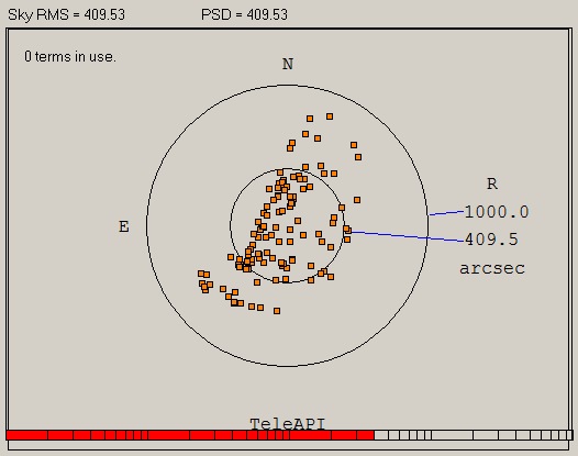
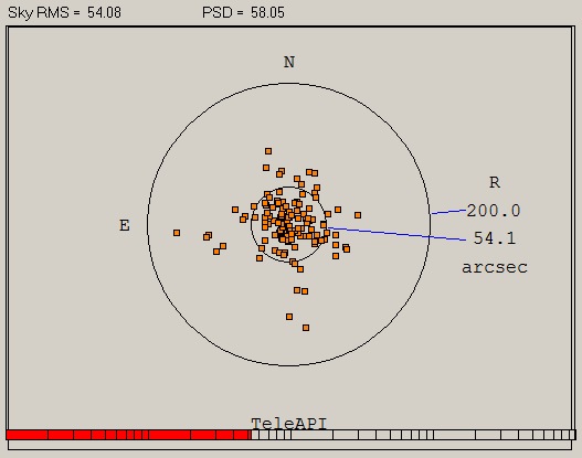
Without TPoint Model the average pointing error of the 121 mapped points is 320 arc secs (5.3 arc mins) with Sky RMS of 410 arc secs (6.8 arc mins). The 'best determined' TPoint incorporating 12 terms (6 equatorial terms, Tube Flexure TX, ACES, ECEC and 3 harmonic terms) reduces Sky RMS down to 47 arc secs (0.7 arc mins). Overall Polar Misalignment is modelled to be 2.4 arc mins.
| Scatter Plot (No Terms Modelled) , 121 data points |
 |
| Scatter Plot with Best Determined TPoint Model 12 terms & 121 data points (6 equatorial terms, Tube Flexure(tan), ACES, ECEC & 3 harmonic terms) |
 |
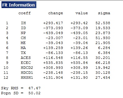
| Fit Information for Best Determined TPoint Model |
 |
| Fit Information for Best Determined TPoint Model |
 |
| TPoint Modelling Results (the Best Determined TPoint Model is shown in bold) |
||||||
| Model | Sky Rms | PSD | Azimuth Adjustment | Altitude Adjustment | ||
| 0 terms | 409 (6.8 arc min) | 409 | ||||
| 2 terms | 394 (6.5 arc min) | 397 | Rotate counterclockwise 4.7 arc min | Lower axis 0.4 arc min | ||
| 6 terms | 322 (5.8 arc min) | 330 | Rotate counterclockwise 4.9 arc min | Lower axis 1.8 arc min | ||
| 7 terms | 168 (2.8 arc min) | 173 | Rotate counterclockwise 4.5 arc min | Raise axis 1.8 arc min | ||
| 8 terms | 152 (2.5 arc min) | 158 | Rotate counterclockwise 4.5 arc min | Raise axis 6.1 arc min | ||
| 9 terms | 101 (1.7 arc min) | 105 | Rotate counterclockwise 4.3 arc min | Raise axis 1.0 arc min | ||
| 10 terms | 69 (1.2 arc min) | 72 | Rotate counterclockwise 4.3 arc min | Lower axis 0.4 arc min | ||
| 12 terms | 58 (1.0 arc min) | 61 | Rotate counterclockwise 4.4 arc min | Lower axis 2.1 arc min | ||
| 16 terms | 54 (0.9 arc min) | 58 | Rotate counterclockwise 4.4 arc min | Lower axis 1.0 arc min | ||
| 21 terms | 53 (0.9 arc min) | 58 | Rotate counterclockwise 4.4 arc min | Lower axis 0.5 arc min | ||
| 12 terms | 47 (0.8 arc min) | 50 | Rotate counterclockwise 4.3 arc min | Lower axis 0.7 arc min | ||
| 14 terms | 47 (0.9 arc min) | 50 | Rotate counterclockwise 4.3 arc min | Lower axis 0.8 arc min | ||
Back to Top
The TPoint Mapping Run indicates that Polar Alignment is off by a few arc minutes and there would benefit in getting my permanently mounted telescope to show a closer Polar Alignment. There is some ambiguity however in what the necessary correction should be.
Azimuth
The Azimuth adjustment indicated by TPoint remains reasonably constant at
between 4.3 to 4.9 arc min
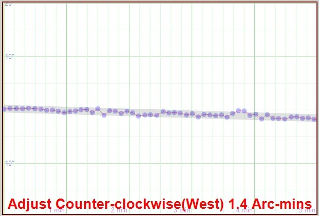
counter-clockwise for different number of model terms. The last Drift
Alignment Check for Azimith using PemPro Polar Alignment Wizard (2018-05-13) indicated that a
1.4 arc min counter-clockwise adjustment was needed. The TPoint number would
normally be considered more accurate.
Star RA Tracking measurements
using PemPro on 2018-05-13 / 2018-05-14 for Periodic Error Assessment also
provide information about star drift in Declination. Following a
star at Dec ~ 0 (2.8 deg) in the Southern Sky (Azim ~ 180 deg) show that
it drifts towards the South which implies that the mount needs to be turned
counter-clockwise !
(the Star Drifts 22 arc sec south in 50.5 minutes,
so alignment Error (in arc mins) =~ 3.8197 * 22 (arc sec) / 50.5 (minutes)
= ~1.66 arc mins, but should this error be compared with TPoint's MA
value of 2.5 arc mins
or with TPoint suggest azimuth correction
of 4.5 arc mins ?)
Star RA Tracking measurements using PemPro on 2018-05-16 / 2018-05-17 for
Periodic Error Assessment provides further information about star drift in
Declination. Following a star at Dec ~0 (2.4 deg) in the
Southern Sky (Azim ~ 180 deg) show that it drifts towards the South which
implies that the mount needs to be turned counter-clockwise !
(the Star
Drifts 23.5 arc sec south in 27 minutes, so alignment Error (in arc mins)
= ~ 3.8197 * 23.5 (arc sec) / 27 (minutes)
= ~ 3.3 arc mins,
but again should this error be compared with TPoint's MA value of 2.5 arc mins
or with TPoint suggest azimuth correction of 4.5 arc mins ?)
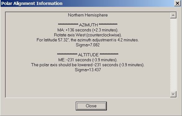
[ Notes: In the Northern Hemisphere, a positive MA means that the pole of the mounting is to the right (East) of due north. When making adjustments to correct for the MA term (polar misalignment in azimuth) you need to rotate about a vertical axis through a larger angle than MA itself. This is because MA is really a rotation about the point Hour Angle = 0, Declination = 0. The factor to inflate MA by before rotating the mount is 1/cos(latitude) ]
Altitude
The Altitude adjustment indicated by TPoint varies considerably with the
model. With 6 terms and 12 to 16 terms the required altitude adjustment is to lower
the axis by 1.0 to 2.1 arc mins, however with 7 to 9 terms the suggested
adjustment is to raise the axis !. In the case of 8 terms the adjustment is to
raise the axis by 6.1 arc mins. An alternate 12 term model (including HCES &
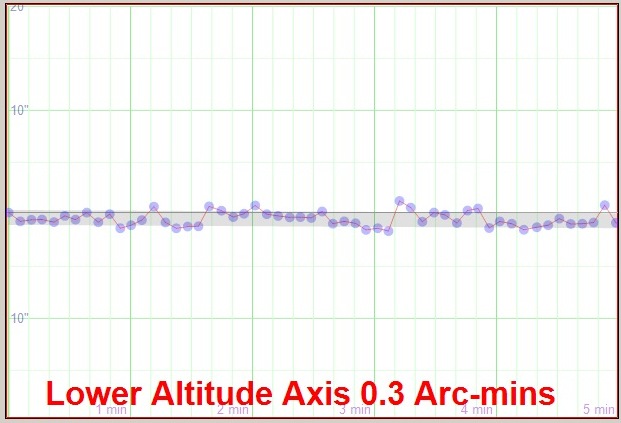
DCEC) suggests to lower axis by 3.9 act mins, The last Drift Alignment Check for Altitude
using PemPro Polar Alignment Wizard (2018-05-13) indicated a requirement to lower the
Polar Axis by 0.4 arc min, subject to uncertainty from Rotation Misalignment. The TPoint number would normally be considered
more accurate, but the direction & size of the adjustment is too variable to be
really useful.
The raise axis cases only occur when Classic Tube Flexure
(TF) term is used. If the alternate/better term Tube Flexure.tan (TX) is used the
suggested altitude adjustment for 8 term case is to lower the axis by 1.5 arc
mins.
[ Notes : The classical tube flexure model, TF, which assumes that the telescope obeys Hooke's Law, is a sine rather than tangent law. In practice there is often a rapid increase in the vertical displacement towards the horizon, and it is sometimes found that the present term, TX, is a better approximation than TF]
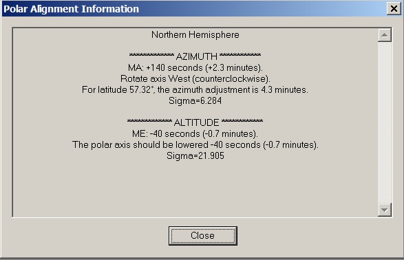
Azimith/Altitude (Best Determined)
Finally a Best Determined TPoint was settled upon (12 terms including Tube
Flexure(TX), ACES, ECEC & 3 harmonic terms) that have a Sky RMS of 47 arc secs
and indicate a Polar Adjustment involving a 4.3 arc min counter-clockwise
rotation and a 0.7 arc min (40 arc sec) lowering of the axis.
[ Note : An
alternate 12 term model using HCES/DCEC instead of ACES/ECEC has a Sky RMS of 53
arc secs and indicate a Polar Adjustment involving a 4.2 arc min
counter-clockwise rotation and a 3.9 arc min lowering of the polar axis.]
| TPoint Polar Alignment Information | ||||||
| Model | Sky Rms | PSD | Azimuth Adjustment | Altitude Adjustment | ||
| 0 terms | 409 (6.8 arc min) | 409 | ||||
| 2 terms | 394 (6.5 arc min) | 397 | Rotate counterclockwise 4.7 arc min | Lower axis 0.4 arc min | ||
| 6 terms | 322 (5.8 arc min) | 330 | Rotate counterclockwise 4.9 arc min | Lower axis 1.8 arc min | ||
| 7 terms | 168 (2.8 arc min) | 173 | Rotate counterclockwise 4.5 arc min | Raise axis 1.8 arc min | ||
| 8 terms | 152 (2.5 arc min) | 158 | Rotate counterclockwise 4.5 arc min | Raise axis 6.1 arc min | ||
| 9 terms | 101 (1.7 arc min) | 105 | Rotate counterclockwise 4.3 arc min | Raise axis 1.0 arc min | ||
| 10 terms | 69 (1.2 arc min) | 72 | Rotate counterclockwise 4.3 arc min | Lower axis 0.4 arc min | ||
| 12 terms | 58 (1.0 arc min) | 61 | Rotate counterclockwise 4.4 arc min | Lower axis 2.1 arc min | ||
| 16 terms | 54 (0.9 arc min) | 58 | Rotate counterclockwise 4.4 arc min | Lower axis 1.0 arc min | ||
| 21 terms | 53 (0.9 arc min) | 58 | Rotate counterclockwise 4.4 arc min | Lower axis 0.5 arc min | ||
| ACES-ECEC | ||||||
| 12 terms | 47 (0.8 arc min) | 50 | Rotate counterclockwise 4.3 arc min | Lower axis 0.7 arc min | ||
| 14 terms | 47 (0.9 arc min) | 50 | Rotate counterclockwise 4.3 arc min | Lower axis 0.8 arc min | ||
| HCES-DCEC | ||||||
| 12 terms | 53 (0.9 arc min) | 56 | Rotate counterclockwise 4.2 arc min | Lower axis 3.9 arc min | ||
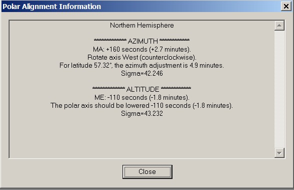
| Polar Alignment Information based on 6 term TPoint Model | ||
 |
||
|
|
||
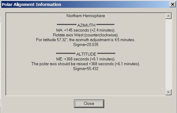
| Polar Alignment Information based on 8 term TPoint Model (a) (6 equatorial terms, plus Fork & Classic Tube Flexure ) |
||
 |
||
|
|
||
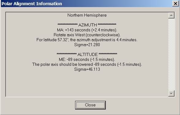
| Polar Alignment Information based on 8 term TPoint Model (b) (6 equatorial terms, plus Fork & Tube Flexure(tan) ) |
||
 |
||
|
|
||
| Polar Alignment Information based on 16 term TPoint Model (6 equatorial terms, Fork & Tube Flexure plus 8 harmonic terms) |
||
 |
||
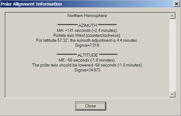
| Polar Alignment Information based on the 'best determined' TPoint Model
(12 terms) (6 equatorial terms, Tube Flexure(tan), ACES, ECEC & 3 harmonic terms) |
||
|
|
||
| Polar Alignment Information based on alternate TPoint Model
(12 terms) (6 equatorial terms, Tube Flexure(tan), HCES, DCEC & 3 harmonic terms) |
||
 |
||
| PemPro PAW - Last Azimuth Check (2018-05-13) | ||
 |
||
| PemPro PAW - Last Altitde Check (2018-05-13) | ||
 |
||
Back to Top
| This Web Page: | Notes - Session 611 (2018-05-17) |
| Last Updated : | 2023-11-29 |
| Site Owner : | David Richards |
| Home Page : | David's Astronomy Web Site |