David's Astronomy Pages
Clair Dome Observatory - Scoping, Design &
Construction
Observatory
Notes
Main
Home
Page
Equipment
David's Astronomy Pages
|
Observatory |
Notes Main |
Home Page |
Equipment |
This page records the scoping, design, construction & commisioning of my new dome observatory in 2018, and its susequent maintainance and operation (2019-2022).
| New Dome Observatory (Clair 3) |
 |
Back to Top
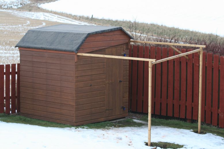
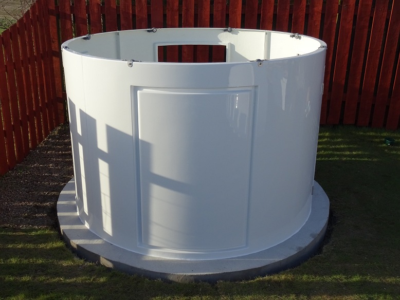
After using my roof-off roof observatory for some 21 years at 3 different sites and struggling badly with it during its two final seasons (2016-2017) I decided that in early 2018 that I would replace it with a completely new observatory. The plan is to get a 2.2m dome observatory with rotation and shutter drives. The observatory would be placed on either a square, octagonal or circular concrete pad, on pretty much the same site as the existing observatory. Justification and aims for the new observatory are listed in a following section.
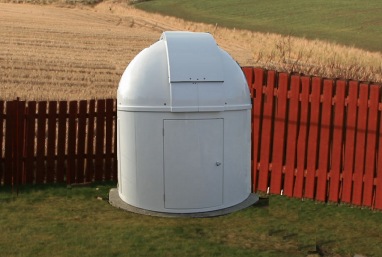
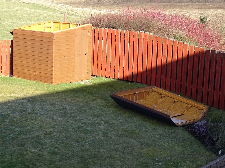
Photos below show the existing roll-off roof observatory together with two photoshopped views of how the new dome observatory might look.
| Previous Roll-Off Roof Observatory | Mock-Up View of New Observatory | Alternate Mock-Up of New Observatory | ||
 |
 |
 |
Back to Top
I had 3 main justifications/aims for the observatory :
1) Resolve 5 specific issues associated with the Clair 2 roll-off roof observatory:
- difficulties in opening/closing current observatory roof
(roof is increasingly difficult to move due to gradual warping of the two
sides, causing wheels to fall off the wall rails)
- safety
issues associated with opening/closing 'stiff' roof (potential for back, shoulder or
hamstring injury)
- safety issue associated with deterioration
(rot) in one of the roll-off support stands (potential for crush injuries if
roof collapses)
- buffetting of telescope by wind with
consequential poor imaging in anything more than a light breeze
(buffetting problems were magnified in 2009 when a new roof-off was built and
a new larger scope (12" LX200) was installed
this had the
combined affect of exposing the telescope to more wind which has reduced the
quality of certain data and
reduced the number of nights
when the scope can be operated)
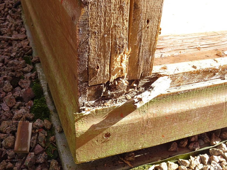
- gradual deterioration (rot)
& water ingress in parts of the 21 year old shed frame
2) Provide
additional capability and
opportunities from a new Clair 3 dome observatory:
- increase astronomical observing/imaging time by being easier to
operate and by being less sensitive to weather conditions
- allow
secondary scope & camera to remain attached to the main telescope between
sessions making setup quicker and more reliable
(in
previous roll-off roof observatory the secondary scope & camera has
to be mounted, connected, disconnected & dismounted at each session)
- reduce
number and length of visits to the observatory by increasing remote
operation capability (e.g. opening/closing roof remotely)
-
create opportunity to improve observatory electrics, wiring, cabling, communications
and lighting
- provide a robust weather resistant structure requiring
less maintainence.
- allow fully automated operations in due course (entire session run from a pretty much a single mouse click)
3) Help meet specific future observing plans
- exoplanet transits
- high resolution planetary imaging
- solar observing
Back to Top
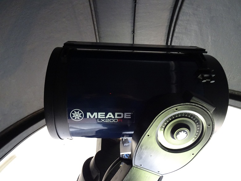
The outline plan for the new Dome Observatory was for it to sit in approximately the same location as the existing Roll-Off Roof Observatory, but offset slightly to allow for a new pier base and to position it slightly further from boundary fencing to allow room for up to 2 bays. The new observatory will reuse the existing armoured Power Cable and use the existing Telescope and Camera equipment (12" LX200 / 80mm APO, ST-10XME / ZWO ASI178MC)
The initial outline plan view of the new observatory is shown below. The precise offset from existing observatory, the precise southerly pier offset from dome centre, the pad size/shape and the positions of the observatory door and bay(s) will subject to later revision as design & planning progressed..
| Initial Outline Plan for New Observatory |
 |
Back to Top
The key project decisions that were made during early 2018 were : :
The decision made under each topic and the rationale is described below:
Back to Top
An outline project plan was maintained during the planning & construction
phases. An important part of the planning effort was the recognition of
key dependancies between different decisions and tasks.
The actual time
line for the completed project is shown below
Completed
- 2017-12-10 Project Conception "New Observatory
in 2018"
- 2018-01-10 Decide key
dome
specifications, 2.2m Full Height, 2 bays, White
- 2018-02-18
Agreement to proceed
- 2018-02-19 Order 2.2m dome observatory &
accessories from Pulsar Observatories
- 2018-03-26 Remove existing
observatory (including removal of roll-off supports & metal pier, photos
-
2018-04-02 Dig hole for new pier base and footings for the observatory's
concrete pad, photos
-
2018-04-03 Contract local concrete supplier to arrange delivery of
1.2-1.5 cu.m of concrete
-
2018-04-05 Construct and level circular former for concrete pad
-
2018-04-06 Recieve Volumetric-Mix Concrete, wheelbarrow concrete and pour
into pad shuttering
- 2018-04-10 Deliver Pier to local metal
fabricator/blacksmith to reduce its height
- 2018-04-10 Receive dome
observatory, this came 7 weeks after order placement
- 2018-04-11
Survey north alignment and pier position
- 2018-04-11 Finalise required
Pier Height Modification
- 2018-04-12 Consult electrician regarding
power supply for new observatory
- 2018-04-10 Contract local metal
fabricator/blacksmith to reduce the height of current metal pier
-
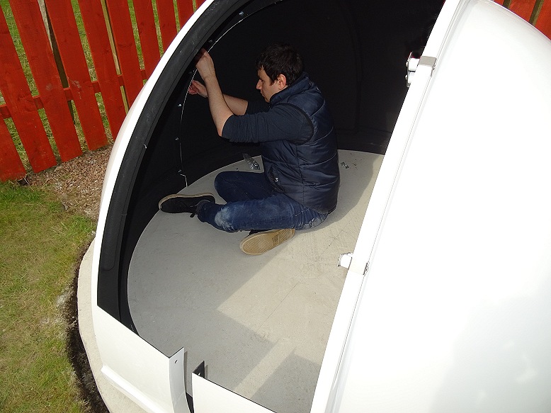
2018-04-19 Self install Dome
Observatory (with
help from son)
- 2018-04-21 Install & hook up power panel
-
2018-04-28 Drill holes in Concrete Pier Base, Install Bolts,
-
2018-05-01 Recieve Shortened Pier from Fabricated/Blacksmith
-
2018-05-02 Install
pier
- 2018-05-02 Install Telescope.
Back to Top
6 potential issues were identified prior to start of the project
A further particular issue was identified during constuction/commissioning
These potential issues and the work undertaken to address/solve them is discussed below:
Back to Top
A study was conducted to look at the number of power sockets and number of ethernet, serial & usb connections. This was extended to look at the power requirments of the all equipment that was envisioned to be used in the new observatory.
| Power | Direct | Indirect | ||||||
| Set | Equipment | Sockets | Ethernet | Serial | USB | USB | Notes | |
| Set 1 | Observatory Computer | 1 | 1 | (3) | ||||
| Set 1 | Computer Mouse | 1 | ||||||
| Set 1 | Dome Controller | 1 | 1 | |||||
| Set 1 | LX200 Telescope | 1 | 1 | 1 | USB to Serial | |||
| Set 1 | SBIG Camera | 1 | 1 | |||||
| Set 1 | Optec TCF-S Focuser | 1 | 1 | 1 | USB to Serial | |||
| Set 1 | ASI178MC Camera | 1 | ||||||
| Set 1 | Dew Heater | 1 | ||||||
| Set 1 | USB Hub 1 | 1 | 1 | (4) | ||||
| Set 2 | AllSky Laptop | 1 | 1 | (2) | ||||
| Set 2 | Computer Mouse | 1 | ||||||
| Set 2 | AllSky Archive Drive | 1 | ||||||
| Set 2 | Oculus AllSky Camera | 1 | 1 | |||||
| Set 2 | Oregon Scientific Weather Stn | 1 | ||||||
| Set 2 | Aurora Cloud Sensor | 1 | 1 | 1 | USB to Serial | |||
| Set 2 | USB Hub 2 | 1 | 1 | (4) | ||||
| Set 3 | Ethernet Hub | 1 | ||||||
| Set 3 | General | 1 | Hairdryer / Flat Frame Sheet | |||||
| Set 4 | Light | 1 | ||||||
| Total | 14 | 2 | 3 | 11 |
Initial assessment indicates a maximum total observatory power consumption of 1728W (7.2A @ 240V), excluding hairdryer & assuming a 50% power efficicieny on AC adapters, or 3328W (13.9A @ 240V) including hairdryer. Hairdryer (1600W, 6.6A) is the single most power-hungery item of equipment in the observatory and should only be used when other equipment isn't drawing high current.
| Power Requirements (click image to view at full size) |
 |
Back to Top
Between 2015 and 2017 an always-on 'AllSky Computer' situated in the observatory has been used to control the capture and processing of AllSky Images, between sunset and sunrise each night. During observing sessions (but not in between times) the 'House Computer' captured weather station data (temperature, humidity, wind and pressure) and the 'Main Observing Laptop' captured sky temperature, cloud and rain data when an observing session was being conducted and the observatory the roof was open (which exposed the Cloud Sensor to the night sky).
In the new observatory it is intended that the 'AllSky Computer' takes on the role of capturing all weather and environmental data on a 24x7 basis, distributing this data to the 'Main Observing Computer' as required.
A number of things have begun to happen to make this possible:
1) A serious bug on AllSky imaging control program has been fixed and allows
the AllSky laptop to run 24x7 without the AllSky Program and/or the laptop
crashing.
2) A 4-port USB hub has been bought and connected to one of the
two USB ports on the 'AllSky Computer'. The 4 ports will be used for
a) Mouse, b) Oculus AllSky Camera, c) USB Communication Hub for talking
with WMR180 base station d) Aurora Cloud Sensor
3) The USB Hub can be powered, but it is not yet known whether it will
actually need to be powered or not, as the only device definately needing
additional power is an external USB hard drive (used for Archiving AllSky
images) which will be run directly from the other USB port on the laptop.
4) A Weather Station program (VMS), USB Communication Hub and my weather data
repeater program have been installed on the 'AllSky' Computer and have run for 10
hours plus. Testing continues but so far the VMS program running on
'AllSky laptop' has been shown to be able to succesfully access and read weather
data from the WRM180 base station sitting on my kitchen window sill, and
forward the data to the Observatory Computer (for recording and information
purposes) and to the AllSky Control Program (for annotating processed AllSky
Images)
5) Addition of Graphs to VWS Display to show the desired weather information, and change Jpg file settings to output Jpg files at regular intervals (say every 20 minutes). A repeater program is then required to transfer weather graphs to the Observatory Control Laptop and/or upload to website (via FTP). This facility being unavailable within the basic edition of the VWS program that I have.
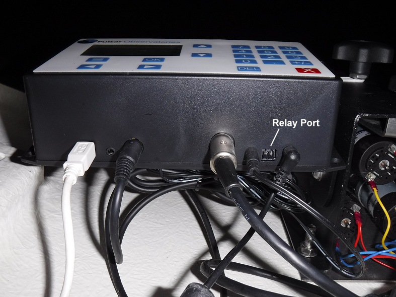
6) Aurora Cloud Sensor Program (v2 and v3) and Driver for Prolific PL2303 USB-to-Serial Adapter have been successfully installed on the AllSky Computer, and have run for 10 hours plus. A repeater program is required to forward Cloud and Rain Information to the Observatory Computer (for recording and information purposes) and to the AllSky Control Program (for annotating processed AllSky Images & Charts).
7) Move Aurora Cloud Sensor unit from inside the observatory to a position outside the observatory (to allow full-time access to the open sky). Cable length is easily long enough, but the method of fixing the Sensor Head outside needs to be defined.
8) Extend routine in AllSky Program to access and display Sky Clarity and Rain data on existing NightSummary Plot.
9) Develop routines to use weather data to optimise telescopic imaging and observations and protect the Dome Observatory and equipment from rain or high winds by closing the Dome's shutter at first sign of adverse conditions.
10) Consideration may need to be given to future options such as adding a new CMOS camera & fisheye lens capable of taking both daytime and nighttime AllSky colour images.
Pictures below show show status of some of these improvements and changes in early 2018..
| Cloud Sensor (2018-01-01) |
||
| Cloud Sensor box in new Outside Position | ||
 |
||
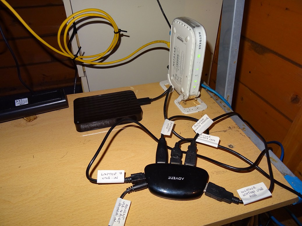
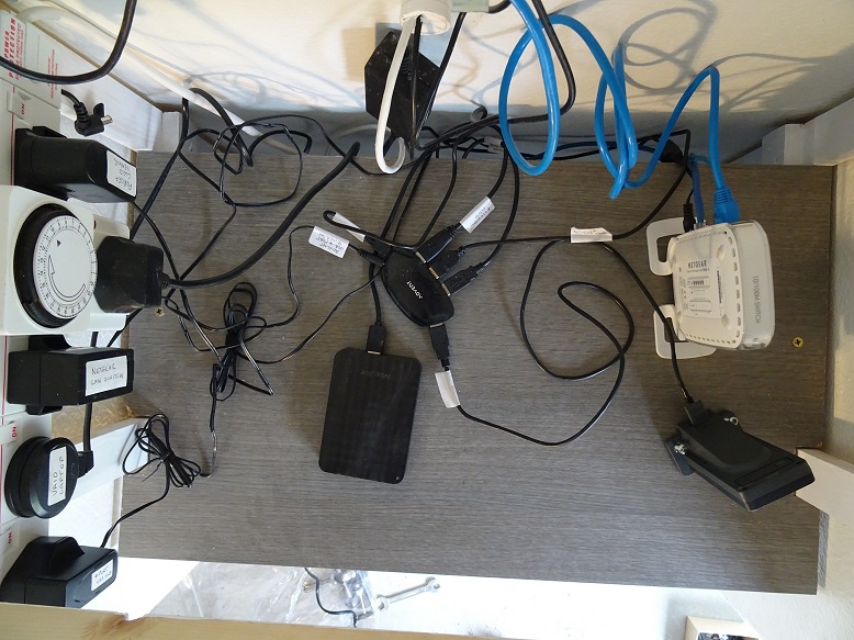
| AllSky Kit & Cabling in
Previous Observatory (2018-01-08) |
||
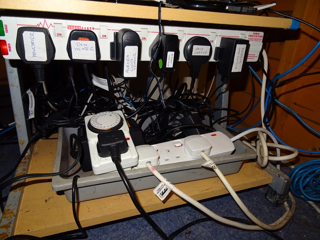
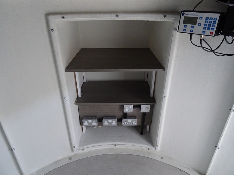
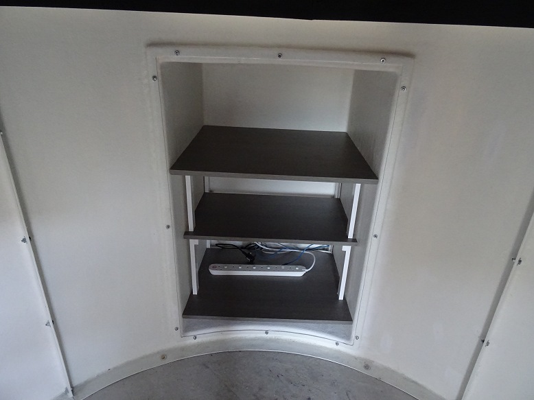
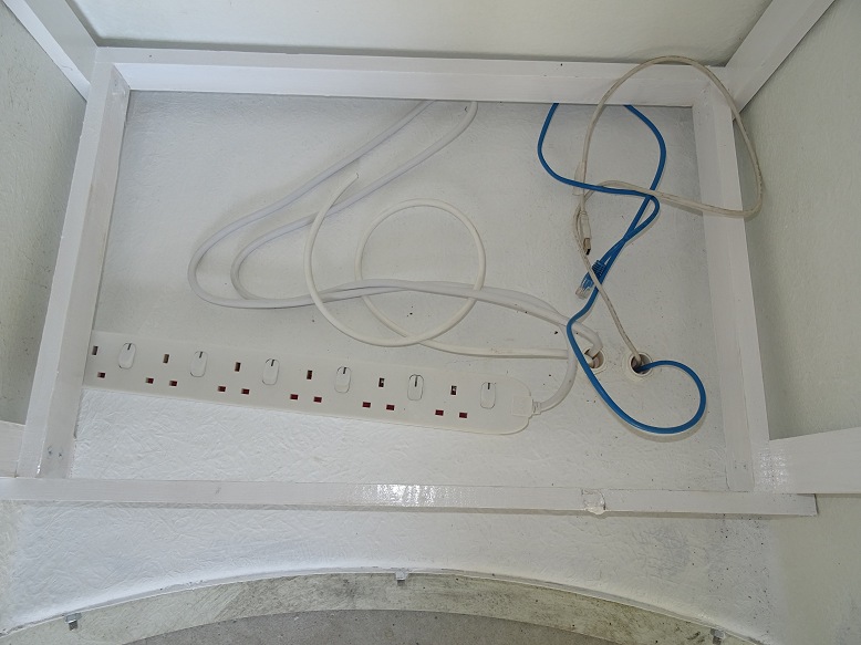
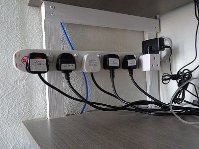
| AllSky USB Hub on middle shelf Comms to Oculus AllSky Camera, Cloud Sensor, Weather Station USB Hub Communicator & External USB Drive |
Front Power Strip for AllSky Laptop & Connected Equipment 4-Port USB Hub, Oculus AllSky Camera Heater Cloud Sensor, External USB Hard Drive |
|
 |
 |
|
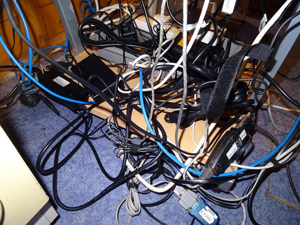
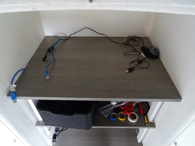
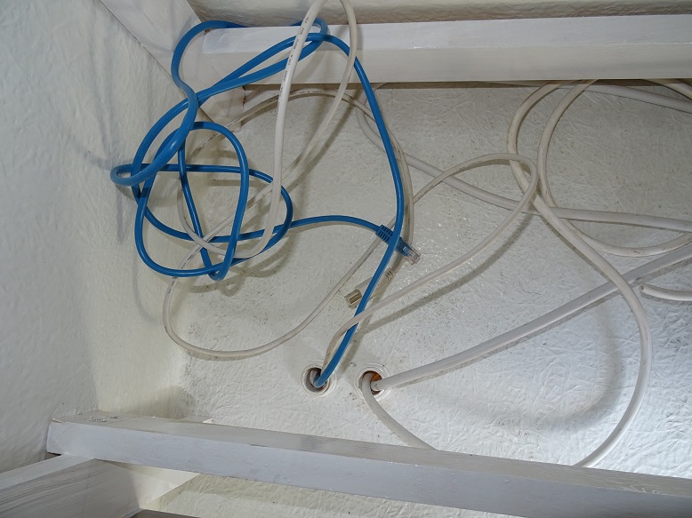
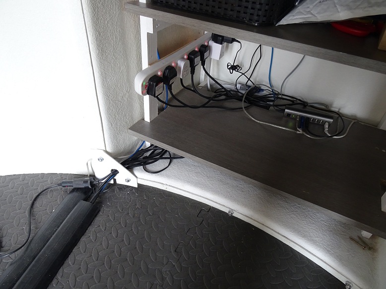
| Nest of Cables on lower shelf / spilling onto floor in previous observatory Power Cables & Data Cables (USB, Serial, Ethernet) this is something that can be hopefully sorted out / improved on in the new observatory |
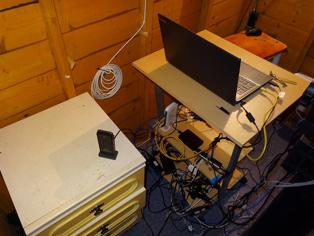
Observatory Desk & Power/Data Hub (right) + USB Hub Communicator to Weather Station in previous observatory (fixed on cabinet in foreground, left) |
|
 |
 |
|
Back to Top
A series of Cabling Plans were drawn up for new observatory and are shown
below.
Telescope Control and Imaging shows two options. Option 1
was one initially used in new observatory and was largely based on system used
in the previous observatory in 2017. Option 2 shows an alternate design in
which a Power/Comm Hub was brough and installed. This is close to
the design that was moved to in late 2018/early 2019 with the purchase of a
Pegasus Powerbox (V1) .
| Telescope Control and Imaging - option 1,
based on existing setup (this was set up used during 2018, after which the setup migrated closer to that in Option 2 below) |
 |
| Telescope Control and Imaging - option 2,
based on using an all-in-one HUB solution (A Pegasus PowerBox & USB Control Hub was installed in late 2018, with LX200 comms & power supply tranferred to Hub in 2019) |
 |
| Observatory Bay 1 - AllSky Imaging, Weather,
Ethernet Hub, Power Board (this is the setup that has been used through 2018-2020) |
 |
| Observatory Bay 1 - Power Panel and
Dome Drive System (a dehumidifier hasn't yet been installed - as of 2020) |
 |
| Observatory Bay 1 - Power Panel and
Dome Drive System (Red Light and Light Rope haven't yet been installed - as of 2020) |
 |
Altair Pegasus
Use of an
Pegasus Ultimate PowerBox USB Control Hub (Altair), or similar system, could
offer me a chance of reducing the cabling going to the telescope. Cost for the
Alatir all-in-one solution is however pretty high (£499) and its not
certain whether it can be justified or not. It would be used
- dew heater
control (2)
- power for focusers (2)
- USB cable to focusers (2)
- USB
cable to ST-10XME camera (1)
It doesn't remove the need for a serial cable to Optec TCF-S Focuser, and may require the Focus Control/Handbox Unit to be mounted on the scope itself, rather than on the pier as at present.
The unit offers no significant benefits however with regard to
-
power for ST-10XME camera (ST-10 uses a special 12V, 12V, 5V AC Adpater
adapter and 5 pin power cable
- power for LX200 (this is can be more
easily supplied by cabling from the pier)
- control cable for the LX200
(this is more easiy supplied by RS232 cable (serial to USB) from the pier
-
USB cable to the ASI178MC camera, which requires a direct camera to computer
connection to achieve the highest possible frame rates
The number of cables going to the Telescope Tube area (serving Imaging
Cameras, Dew Heaters and Focusers) reduces from 7 to 4. This is a saving of 3
cables but at the expense of having extra kit (Optec TCF-S handbox and the
Pegasus Control Hub) attached to the telescope tube/forks by some means.
The Pegasus Powerbox would also reduce the number of required 240v power sockets by
2.
Update
UPB was purchased and
installed on the Observatory Telescope in late 2018. There were a number
of teething problems mainly related to the Power Supply and it was not until mid
2019 that the system was working effectively.
Back to Top
The observatory uses a Windows 7 computer that is hard-wired to many of the control systems and equipment in the observatory, including the Pulsar Dome with Rigel Dome & Shutter control, LX200 GPS telescope & mount, cameras (SBIG ST-10XME & ZWO ASI 178MC) and focusers. Currently the computer is a laptop which is brought into the observatory for each observing session. In due course a dedicated observatory computer will be installed.
In addition to the observatory computer there is a server than manages file storage. All images captured by the observatory computer are stored on the server for processing later.
Finally there is also a separate environmental or weather server that is tied to a weather station (Oregon Scientific WM180R), cloud/rain sensor (Aurora/Eurotech), machine readable online weather forcasts (darksky.net) and an all sky camera (Starlight XPress Oculus 180). The weather computer collects data from the various sources and uploads various charts, graphs and images to the internet and to the local server for display on the observatory web pages. The weather server also monitors changes in the weather and accesses how suitable the weather conditions are for observing and whether it is safe or unsafe for opening the shutter on the observatory dome. This information and certain other weather data is sent to the observatory computer. The weather server also recieves information from the observatory computer about where the telescope is pointing and the location of the next few planned targets. The weather server returns information to the observatory computer about the presence or otherwise of cloud at the scope positon and at each of the next targets. The weather server is currently an old laptop running Windows Vista, and just about manages to keep up with the computing load required, however it may be upgraded to a computer with faster CPU in due coarse.
An observatory management program running on the observatory computer uses information from the weather server, to decide whether to open the observatory dome for automated imaging when the sky is clear and dark, when to pause imaging or move to an other target when cloud encroaches and when to shutdown & close the observatory when heavy cloud, rain or daylight encroaches.
Communication between Observatory Computer and AllSky/Weather Computer is performed across LAN using a number of specific TCP/IP Ports.
Accurate time in the observatory is important for homing the telescope upon startup and other functions in the observatory, such as correctly recording the time that images are acquired. Computer time is kept current by constant updating from time servers on the internet using Dimension 4 software.
Back to Top
Currently certain equipment is left on 24x7 (the observatory dome and the weather server and associated sensors) whilst certain other equipment (Observatory Computer/Telescope/Cameras/Focusers) are physically turned on at the start of each observing session. In due course the turning on/off of equipment may be either automated or at least operated via remote control.
Currently (2018) there is no power back or plan to add any back-up.
Update 2024-02-28.
A UPS Backup to the
Pegasus UPB Powerbox that distributes power to the LX200 Telescope is being
considered as the telescope is the one item in the Observatory where even a very
short power cut create a very significant problem with would result in a
significant effort & delay to a live session in order to resolve and cause
potential damage. This is because the telescope will turn off with out being
parked, requiring its position to be resynced on a known star and a short
mapping run completed. Whilst Program routines can aide the process it has to be
done under strict user supervision & control.
Back to Top
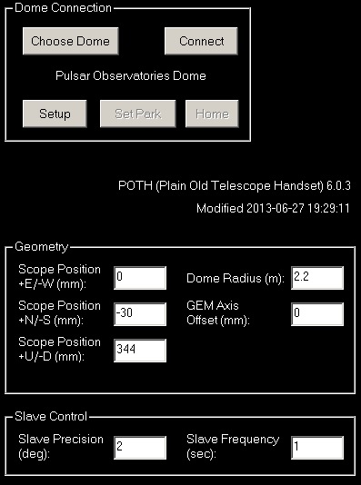
Dome Automation will be enabled using my own Observatory Control Program running on the Observatory Computer with ASCOM & USB connection to the Pulsar Observatories Rigel Rotation Drive and Shutter Drive.
Weather information will be used to ensure the dome shutter is only opened when conditions match specific criteria (no rain and specific limits on cloud, wind and light) and automatically close when conditions become unsafe. POTH.Hub is used to enable the Dome Position to be accurately slaved to the Telescope Pointing during the observing session. [ Note: POTH.Hub was later replaced with DeviceHub ]
The Observatory Control Program has been updated to include a routine to open the shutter prior to observing and rotate it into the wind direction to facilitate the equilibration of the telescope, equipment and dome interior with the ambient air temperature. Sensor information will be used to monitor the temperature difference between the inside of the observatory and the outside air temperature.
The dome will be parked in-between sessions at a position that allows the battery for the Shutter Drive to be topped up by induction charging.
The following online tutorial was found whilst researching Dome automation
which proved useful
:
ASCOM client astronomy
development tutorial and introduction (YouTube)
Later work:
Later work will be listed here....
Back to Top
Image acquisition is can be performed under either manual, semi-automated or fully automated control. Automation is enabled using my own Observatory Control Program. This images a previously prepared target list by orchestrating all of the hardware and software in the observatory by directly monitoring and controlling:
- The LX200 mount for slewing and positioning the telescope with around 10
arc minute precision
- The SBIG camera, 10 position filter wheel and CCDSoft5
for capturing CCD images
- TheSky6 for plate solving and telescope
positioning to around 10 arc minute precision
- Optec TCF-S focuser for
focusing the telescope using my own focusing routines via CCDSoft
and
maintaining focus as temperature and filters change.
- PHD2 for autoguiding
of LX200 scope using 80mm Guidescope and ASI 178MC camera
- Dome opening and
closing
- Dome slewing and tracking (either directly or using POTH.Hub dome
slaving)
- Weather and sky quality monitoring
- Taking dark flats and bias
frames for image calibration
- SharpCap for alternate imaging using
piggybacked 80mm scope and ASI 178MC camera.
Back to Top
The final plan for the new Dome Observatory is similar to original outline plan, but includes a second bay, a circular pad and an adjusted position & orientation. A plan view illustrationof the final plan is shown below
| Final Plan for New Observatory |
 |
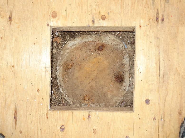
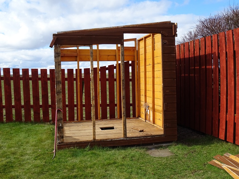
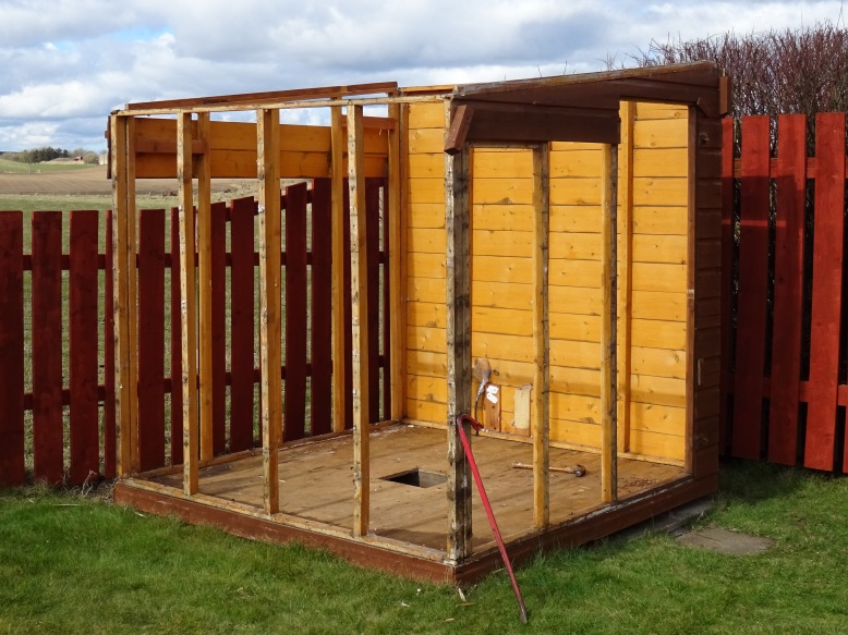
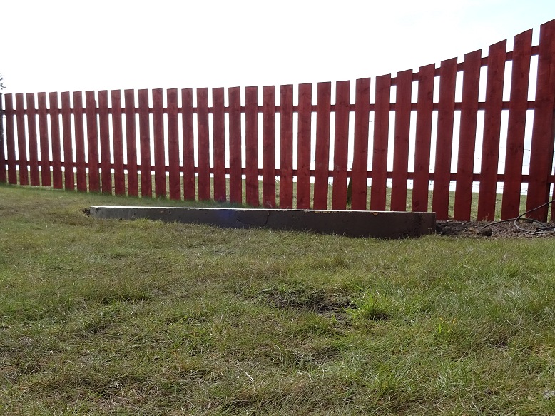
Photos below show the demolition of the existing roll-off roof observatory
and removal its pier.
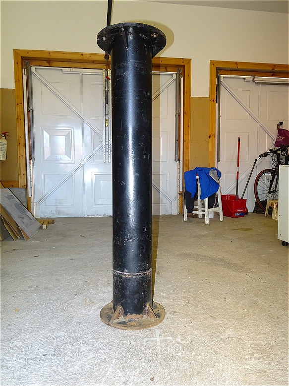
(The existing pier will be cleaned , shortened and
reused in the new observatory)
| Demolishing Old Roll-Off Roof Observatory (2018-03-25 to 2018-03-26) |
||
| Removal of heavy 2009 Roof (removed by taking off a wooden stop block and pushing the roof off the end of the support beams) |
Old Pier Base (North is at top) |
|
 |
 |
|
| Removal of Shed Panels | Removal of Shed Panels | |
 |
 |
|
| Rot at Bottom Corners of Shed | Rot at Bottom Corners of Shed | |
 |
 |
|
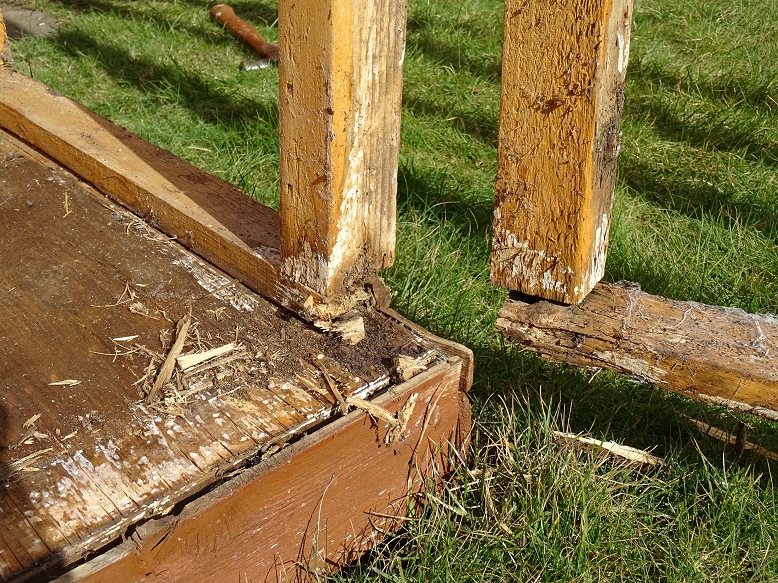
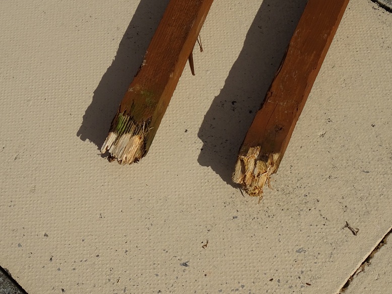
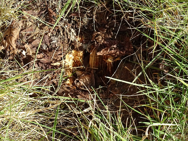
| Rot at Base of Wooden Roof Support Columns (support posts snapped with only a moderate amount of force) |
Rot at Base of Support Column (columns were 9 years old) |
|
 |
 |
|
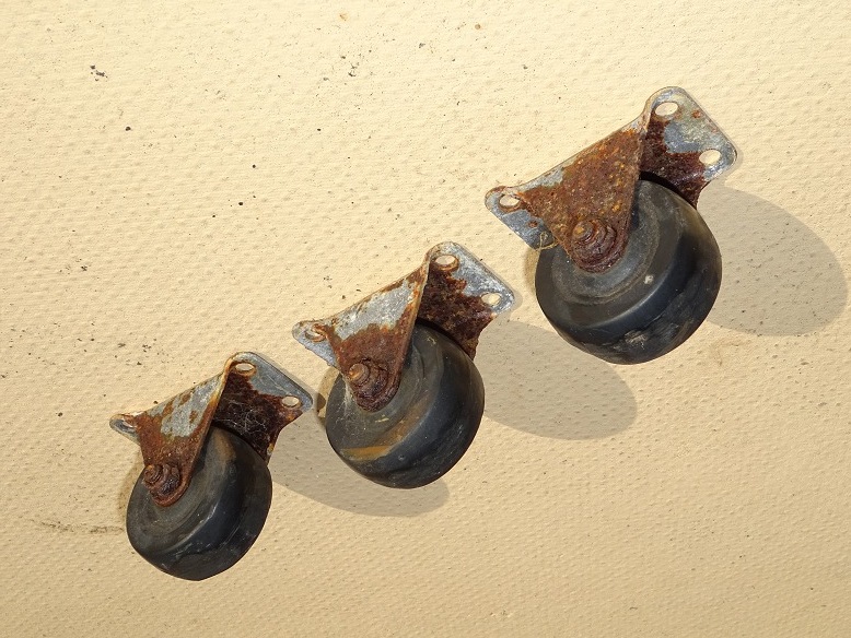
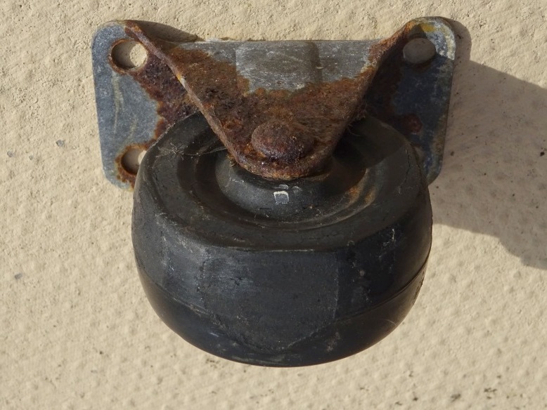
| 3 wheels found to have totally seized up (explains why roof had become so difficult to open/close) |
Seized Up Wheel - detail (Particularly severe abrasion on one of the seized wheels where it has rubbed along the top of the observatory wall) |
|
 |
 |
|
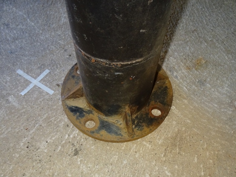
| Old Pier (Old pier is 114cm tall which is too tall for using in the new dome observatory, but will be shortened by 21cm in a fabrication workshop to make it suitable and at 25% of the cost of a new pier ) |
Old Pier Base (Pier base has become rusty after sitting on the ground below the observatory and will need to be thoroughly cleaned up for the using in the new observatory) |
|
 |
 |
|
Back to Top
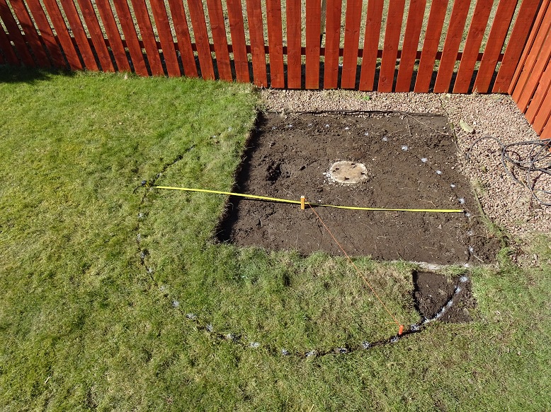
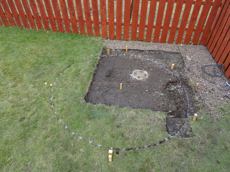
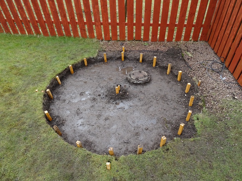
Photos below capture the preparation of the new site / new pad during the first 10 days of April 2018.
| Preparing New Observatory Site (2018-04-01 to 2018-04-03) |
||
| Marking out New Observatory site (2.5m diameter circle. Centre is offset from the old pier base to allow for the new base) |
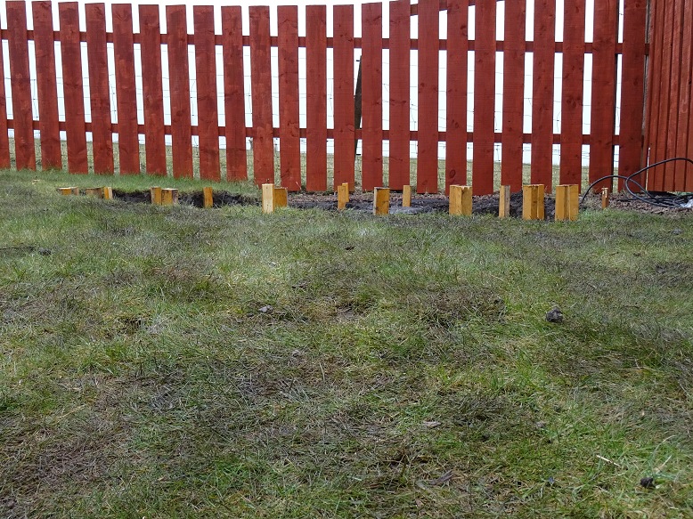
Setting & levelling marker posts for concrete pad (Pad will be 2.4m diameter. The site slopes by 15-20cm from left to right ) |
|
 |
 |
|
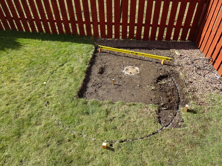
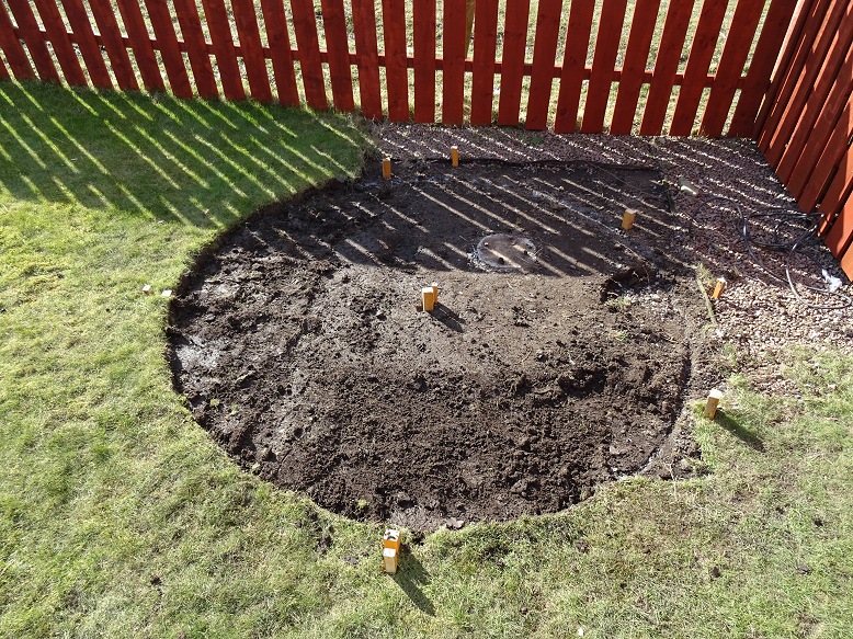
| Surveying Completed (4 survey posts (N,E,S,W) have been added to allow site centre to be re-found using crossed strings after the central peg is removed when digging the new pier base) |
Removal of Turf from Site | |
 |
 |
|
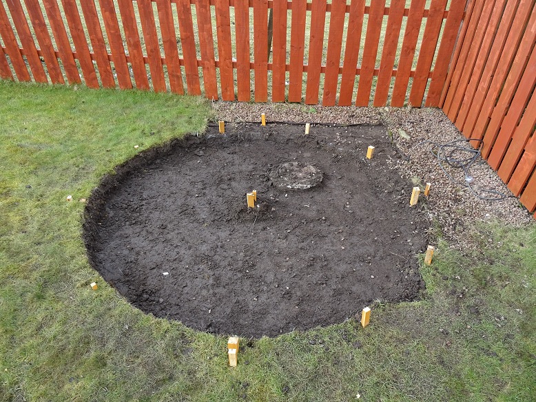
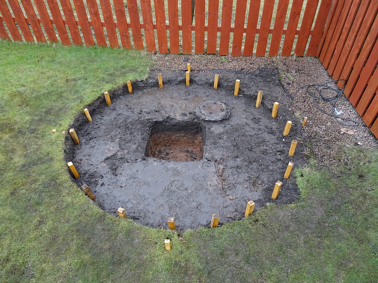
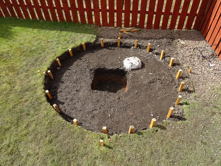
| Hole For Concrete Pad (20cm deep on left around 2-3cm deep on right) Note: centre is disorted in picture due to image perspective |
Posts installed around sides of hole and levelled (later these will support 20cm high circular shuttering with 2.4m diameter) |
|
 |
 |
|
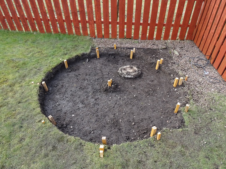
| Further set of posts installed around sides of hole (to further support the shuttering for the 2.4m circular pad) Note: centre is disorted in picture due to image perspective |
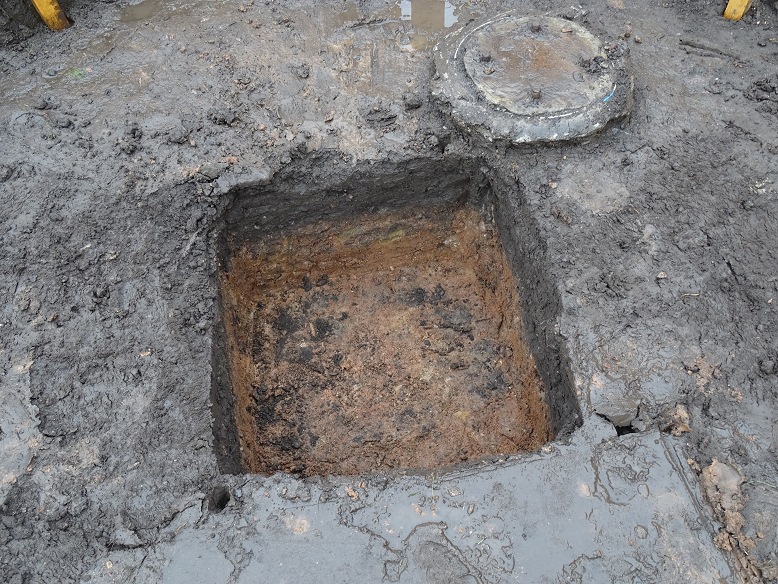
Hole for Concrete Pier Base (pier will be offset from centre of dome by 6.5cm in a southward direction - to the left in image below) |
|
 |
 |
|
| Side View (shows slope of ground across the site) |
Hole for Concrete Pier Base (pier support sits on orange subsoil / glacial till) |
|
 |
 |
|
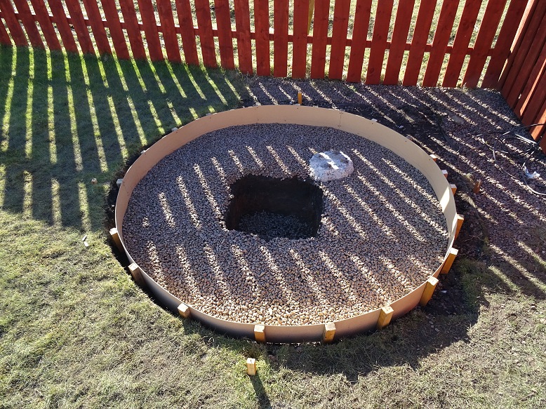
| Site in slightly drier conditions (wet muddy soil has been removed from base of pad, outer parts of old concrete pier have been hacked away) Note: centre is disorted in picture due to image perspective |
Circular Hardboard Shuttering (shuttering installed and screwed tightly to support posts and a gravel base has been laid) |
|
 |
 |
|
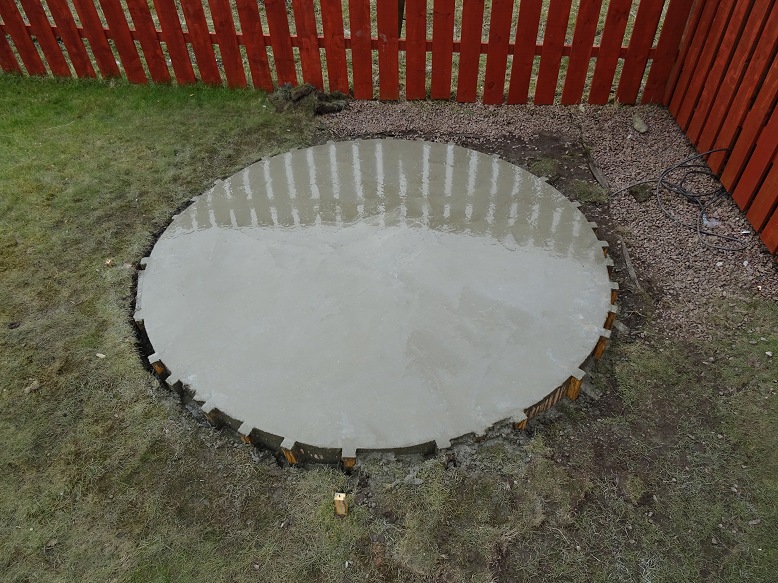
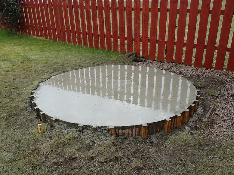
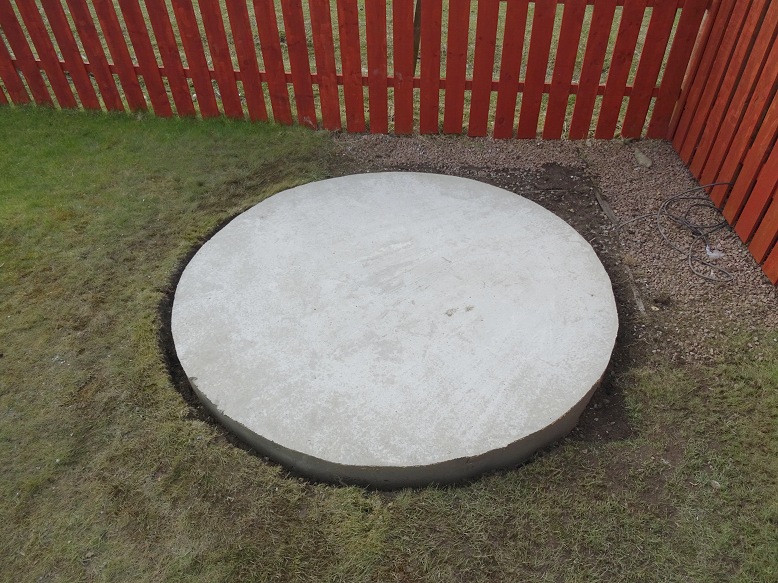
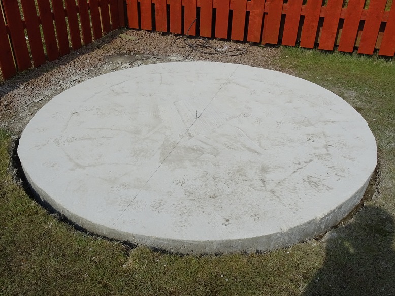
| Concrete Pad (Wet Concrete about 1 hour after pouring) Volume 1.2 cu.m |
Concrete Pad - side view (Wet Concrete about 1 hour after pouring) |
|
 |
 |
|
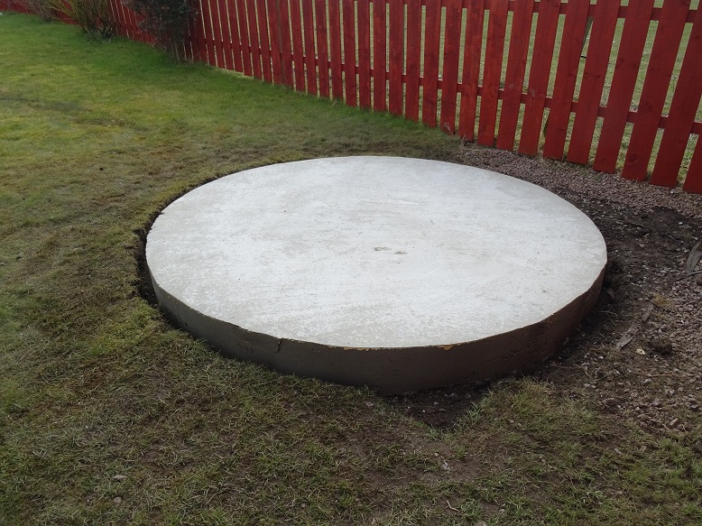
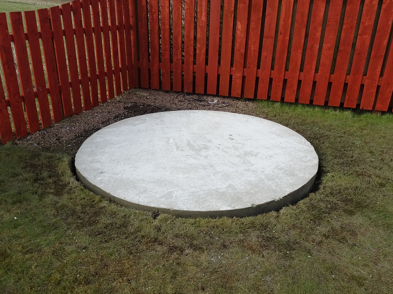
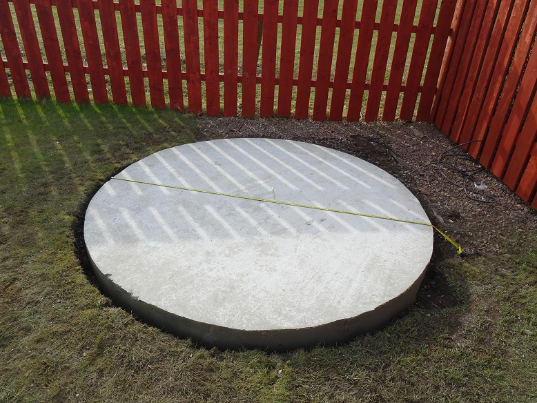
| Concrete Pad - shuttering removed (2 days after pouring) |
Concrete Pad - side view (pad is reasonably circular) |
|
 |
 |
|
| Concrete Pad - edge view (surface is reasonably flat) |
Concrete Pad - alternate view |
|
 |
 |
|
| Determining Centre of Pad (diameter measured in mutiple directions, with arcs of 1 radius length scribed for each diameter line) Note: centre is disorted in picture due to image perspective |
Intersection of Arcs (centre chosen based on eyeballed average intersection of 1 radius length arcs) |
|
 |
 |
|
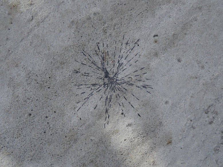
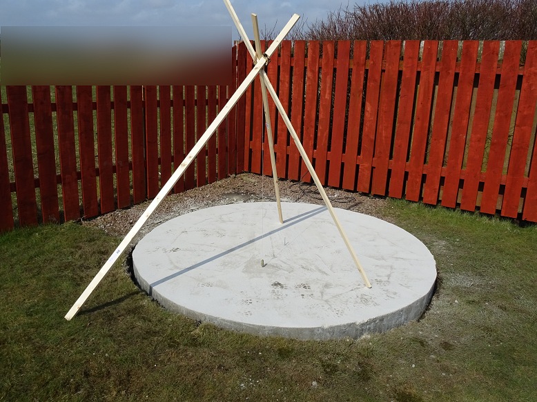
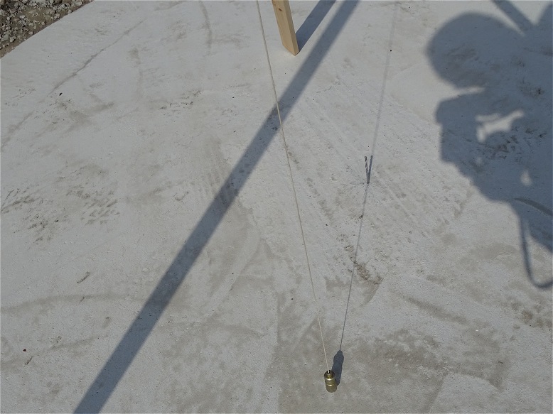
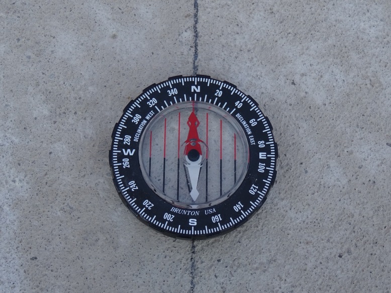
| Determining N-S Alignment (north-south alignment determined using shadow of plumb-bob line at local midday, this was at 01:09:03 BST on this particular day based on my TheSky6 planetarium program) |
Determining N-S Alignment (Picture shows shadow of plumb-bob passing through pre-determined centre of concrete pad. Position was then marked with pencil and a straight line drawn with the aid of a steel ruler) |
|
 |
 |
|
| N-S Alignment (picture showing north-south line scribed on concrete pad) Note: centre is disorted in picture due to image perspective |
N-S Alignment (double checking N-S alignment line using magnetic compass. Magnetic north is 2 deg west of True North at my location) |
|
 |
 |
|
| Existing SWA Power Cable realigned for new observatory (excess cable would be cut later and the cable taken up through the base of one of the bays) |
||
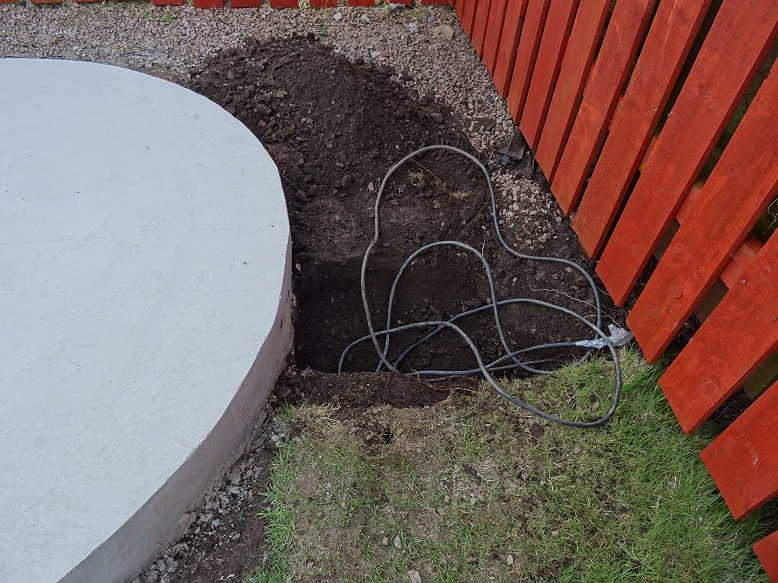 |
||
Back to Top
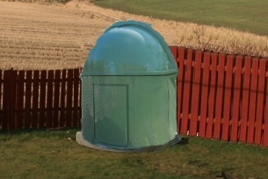
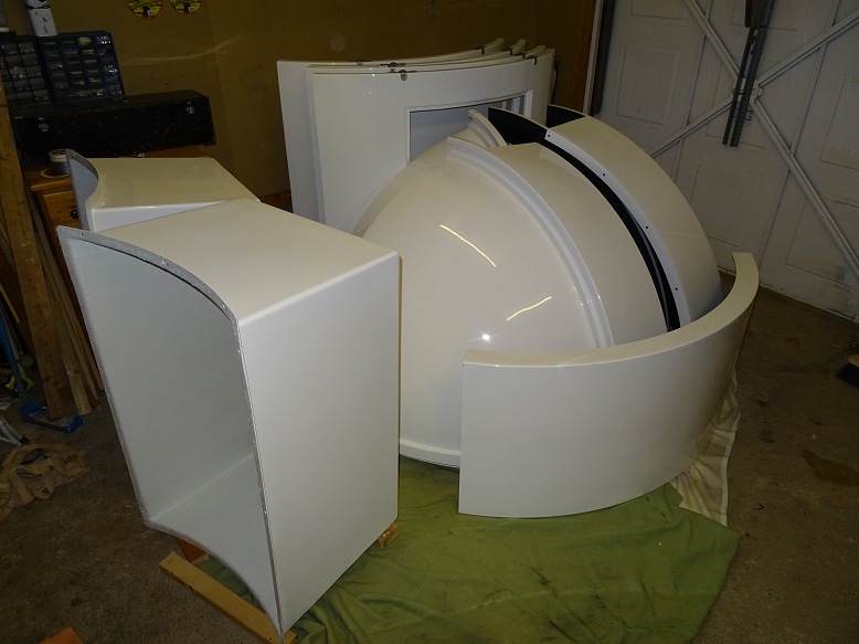
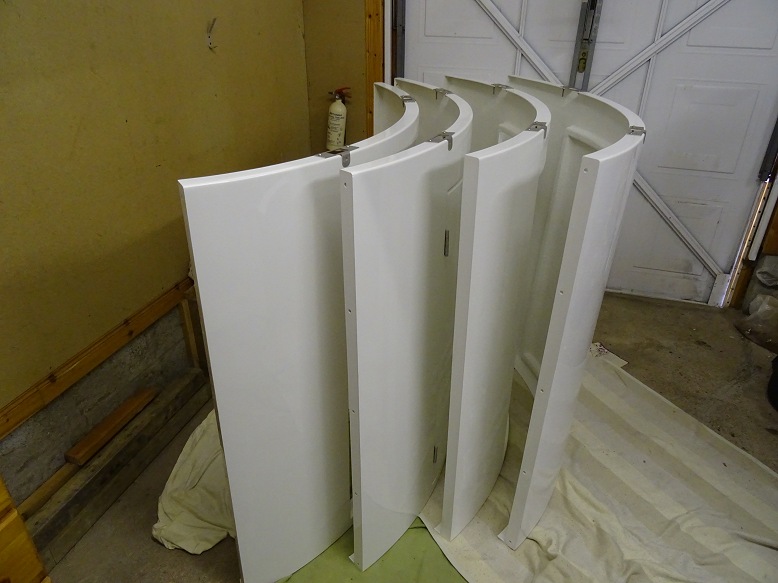
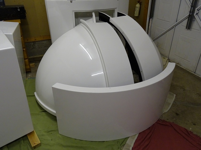
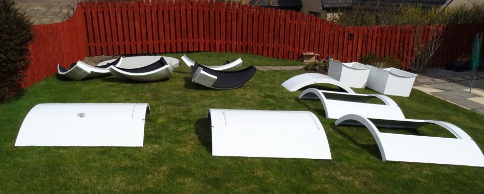
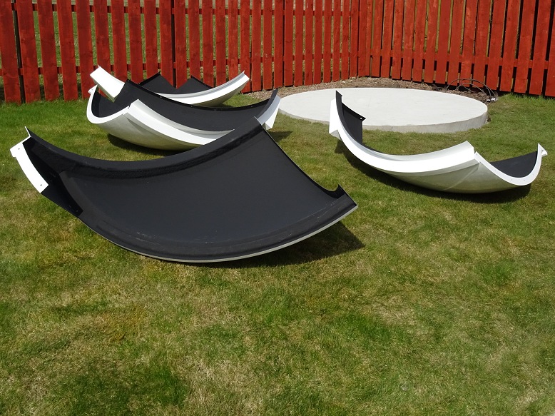
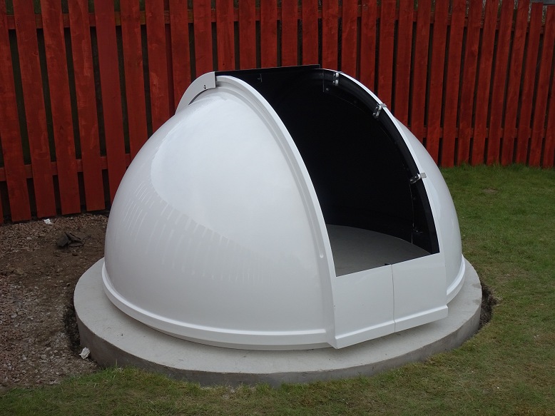
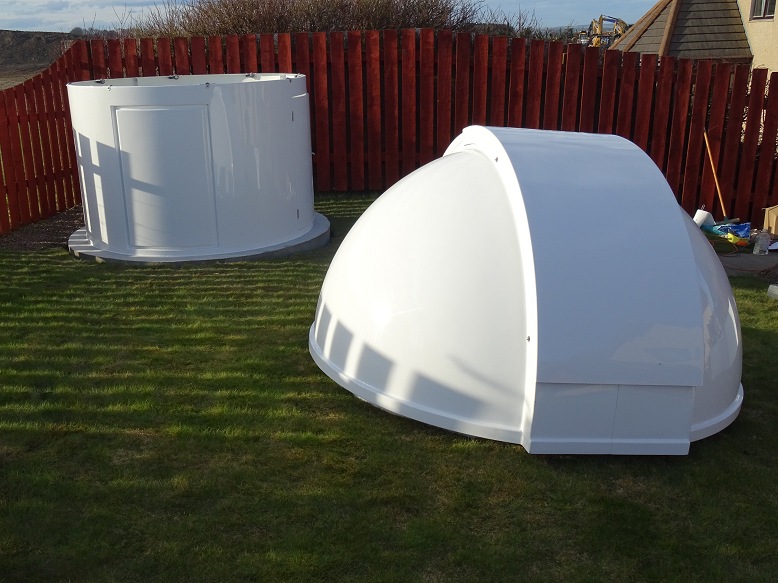
Photos below show various shots of the dome and it components after it arrival in mid April 2018.
| Dome Arrival (2018-04-10) |
||
 |
||
| Wall Panels | Dome Roof Panels | |
 |
 |
|
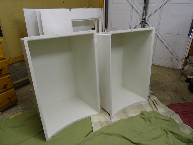
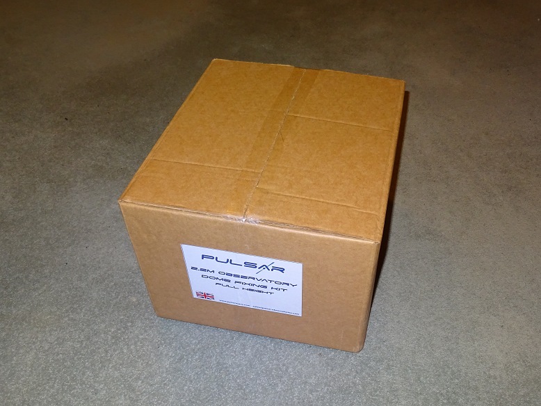
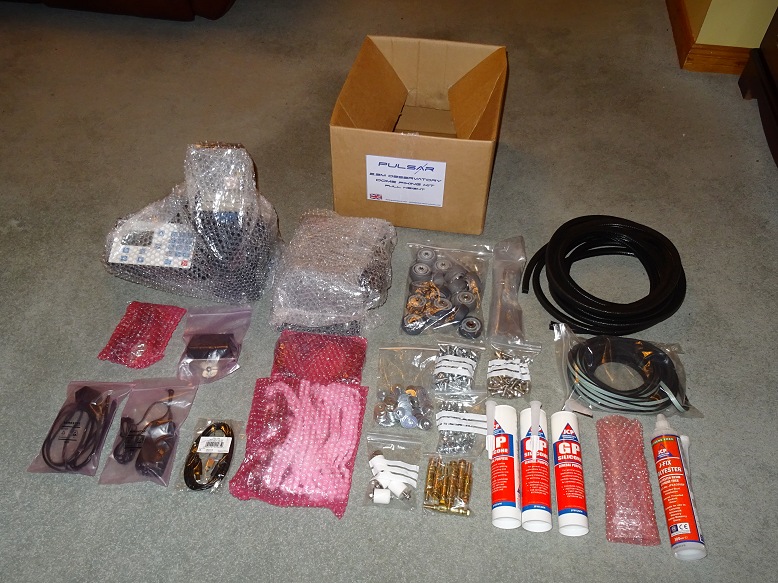
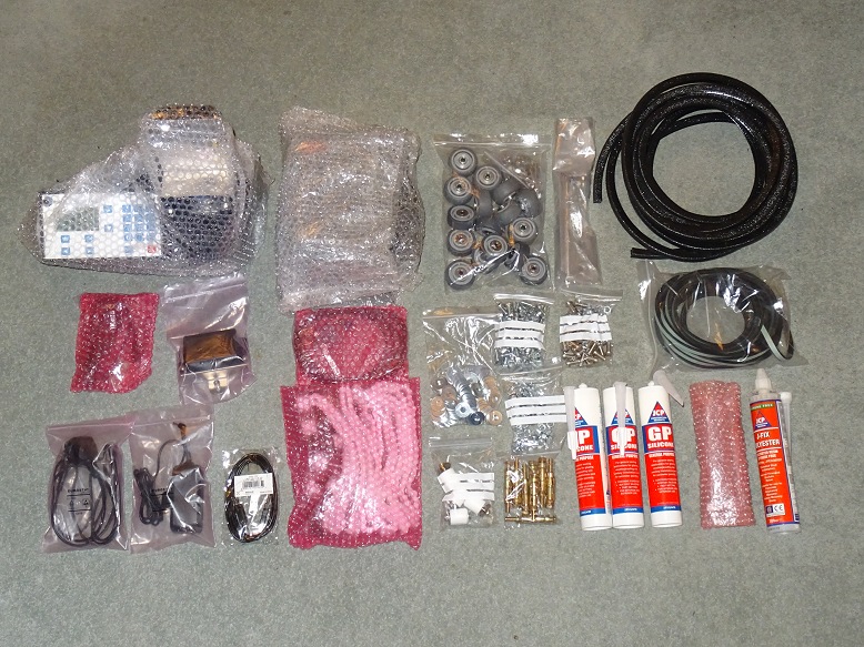
| Two Bays | Box with Dome Fixing Kit plus Dome Rotation & Shutter Drives |
|
 |
 |
|
| Contents of Box (Assembly Instructions, also in the Box, are not shown in this picture) |
Box Contents (from Left to Right) : Rotation Drive & Leads, Shutter Drive & Shutter Chain, Dome Fixing Kit (Wheels, Bolts, Nuts), Security Clamps, Pier Fixing Kit |
|
 |
 |
|
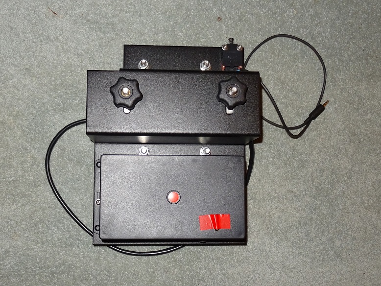
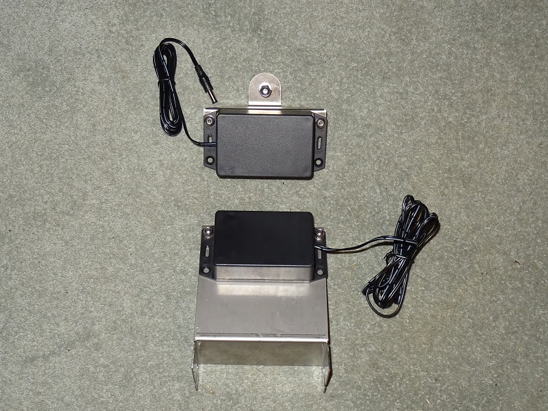
| Shutter Drive - front | Shutter Drive - back | |
 |
 |
|
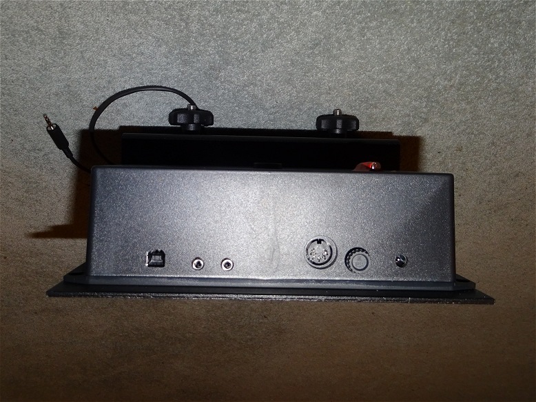
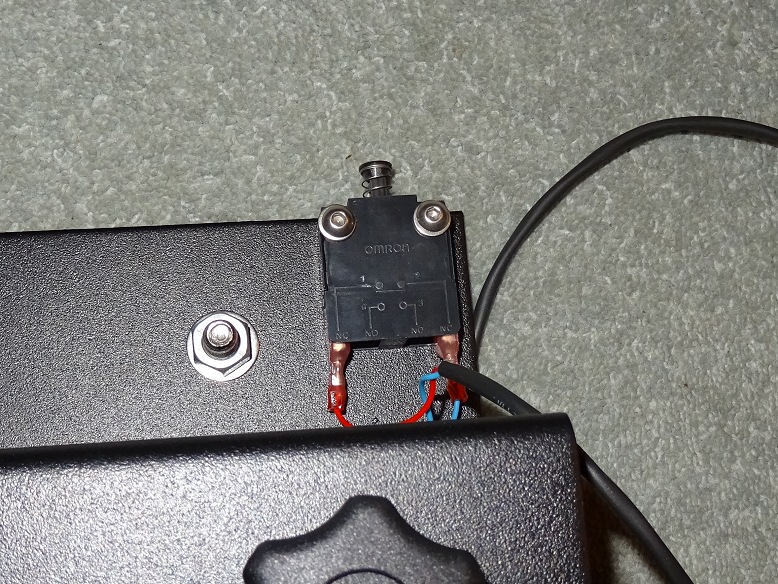
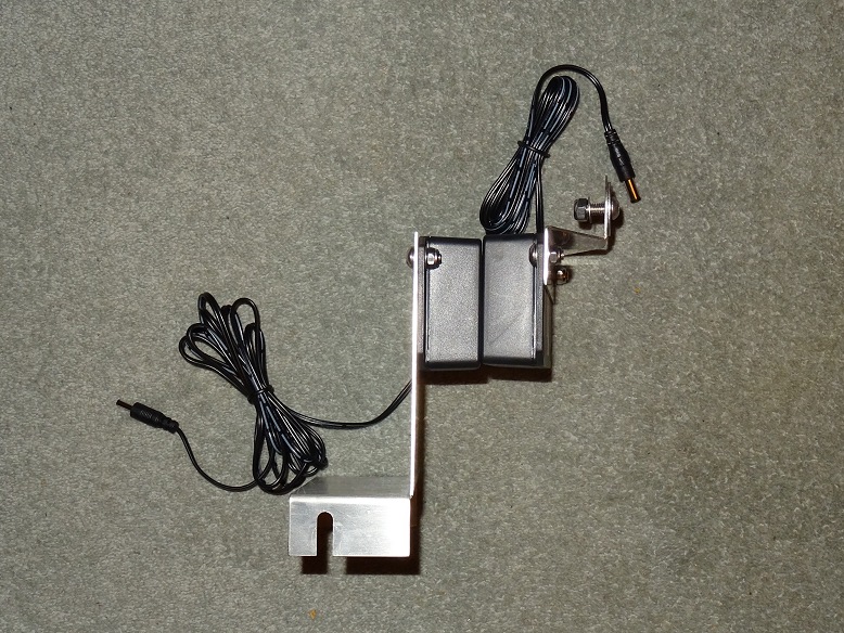
| Shutter Drive - bottom (showing connections) |
Shutter Drive - Limit Switch | |
 |
 |
|
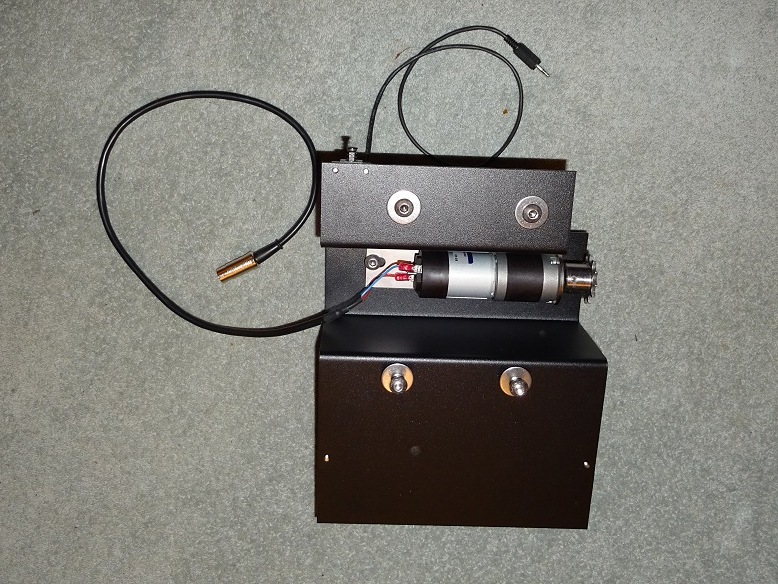
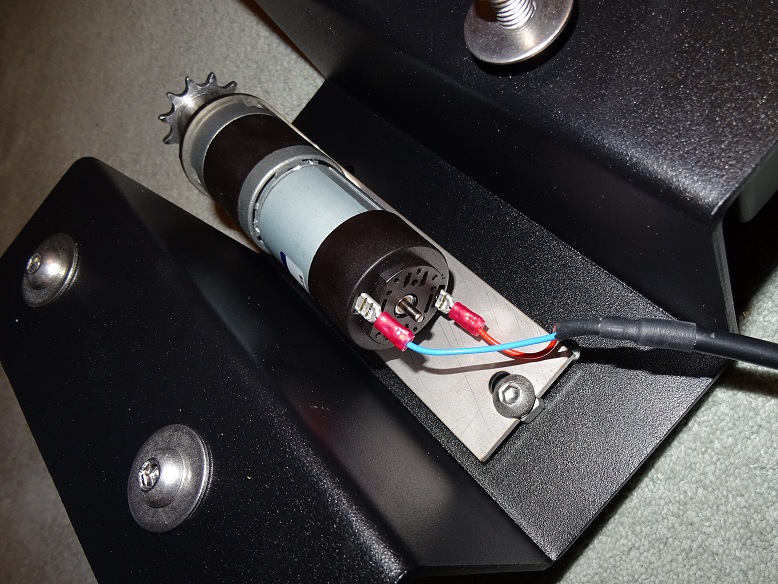
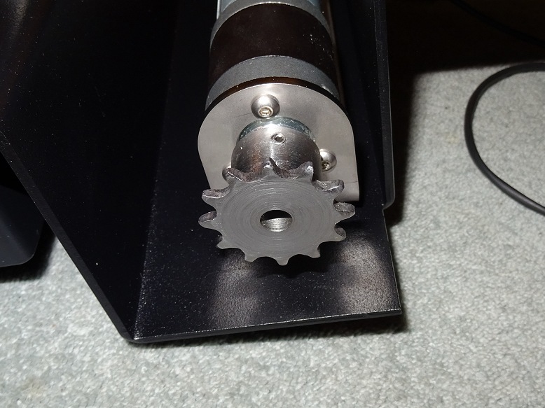
| Shutter Drive Motor | Shutter Drive Motor Spindle | |
 |
 |
|
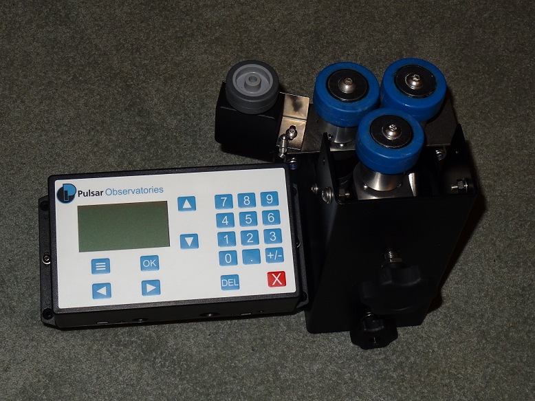
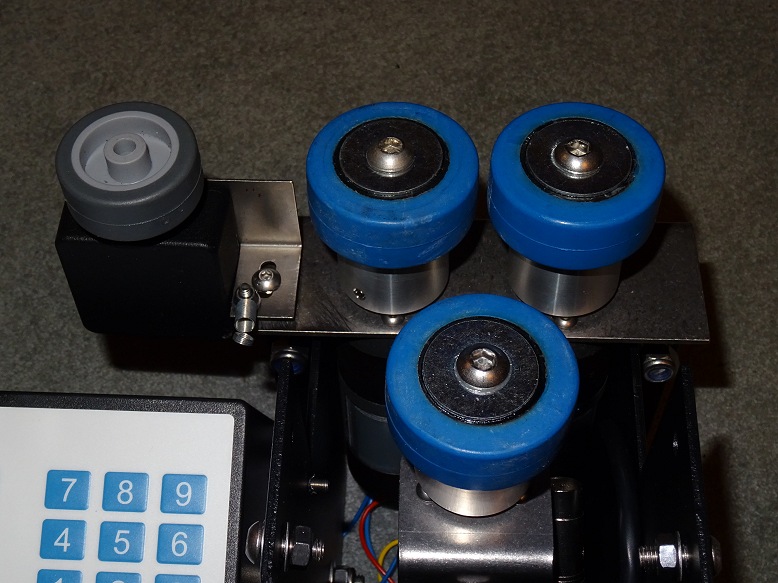
| Rotation Drive & Control Panel | Rotation Drive Wheels (blue) & Encoder Wheel (grey) | |
 |
 |
|
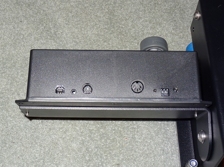
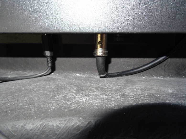
| Control Panel (base of panel, showing connections) |
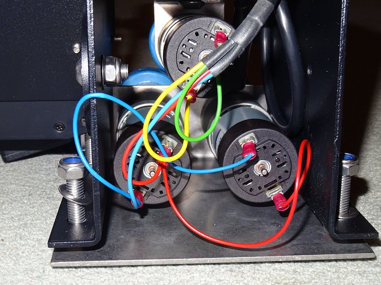
Rotation Drive Motors (bottom view, showing wiring) |
|
 |
 |
|
| Induction Charger | Induction Charger - side view | |
 |
 |
|
Back to Top
Photos below show a selection of work/jobs undertaken in the week between dome arrival (2020-04-10) and dome assembly (2020-04-19).
| Variety of jobs done whilst waiting to assemble the dome | ||
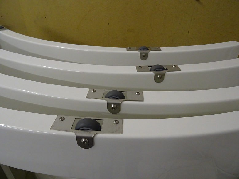
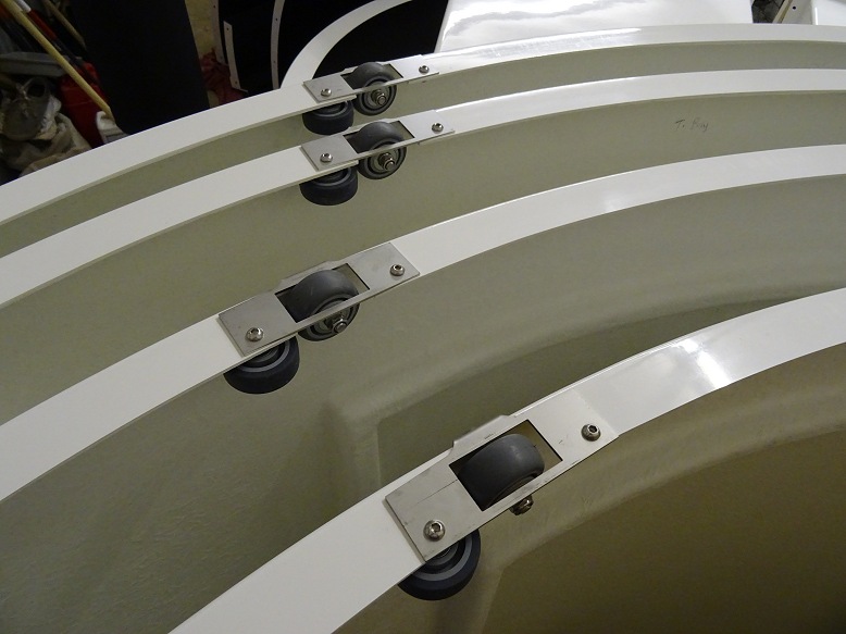
| Dome Wheels Fitted to Wall Quadrants | Dome Wheels | |
 |
 |
|
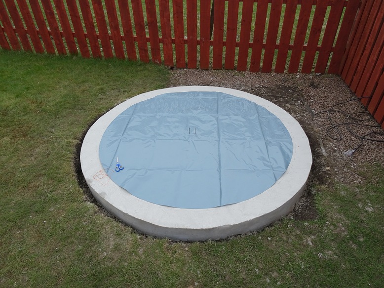
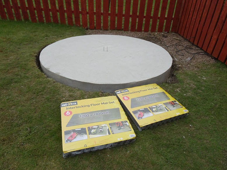
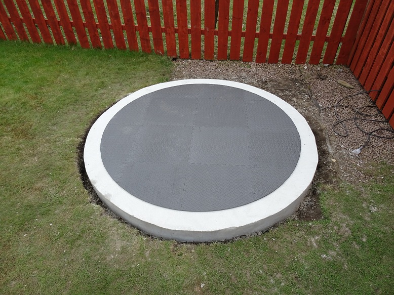
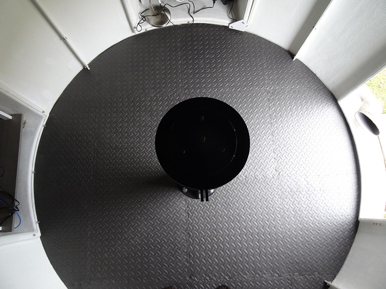
| Damp Proof Membrane (membrane cut to circle) |
Two packs for interlocking floor mats (£10 each from Halfords) |
|
 |
 |
|
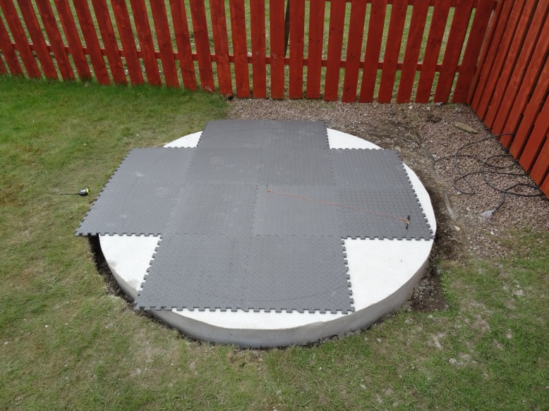
| Laying out 12 interlocking floor mats (this had to be done carefully to ensure that holes could be filled by offcuts of sufficient size) |
Filling in corners with offcuts (pre-cutting the mats was going to be far easier than cutting them with the dome in place) |
|
 |
 |
|
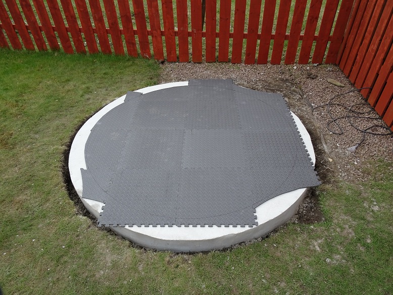
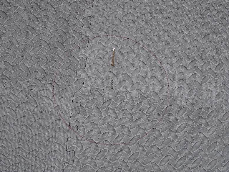
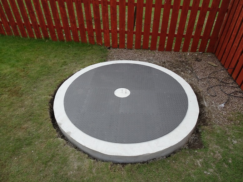
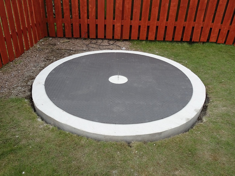
| Floor mats cut to circular shape Note: centre is disorted in picture due to image perspective |
Marking Pier Centre & Base Circumference (6cm offset from dome centre in due south direction |
|
 |
 |
|
| Mats with Pier Cutout (11 inch diameter) |
Completed Mats (final job was to write a number (1 to 16) on the back of the mats to indicate layout) |
|
 |
 |
|
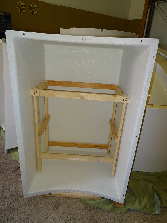
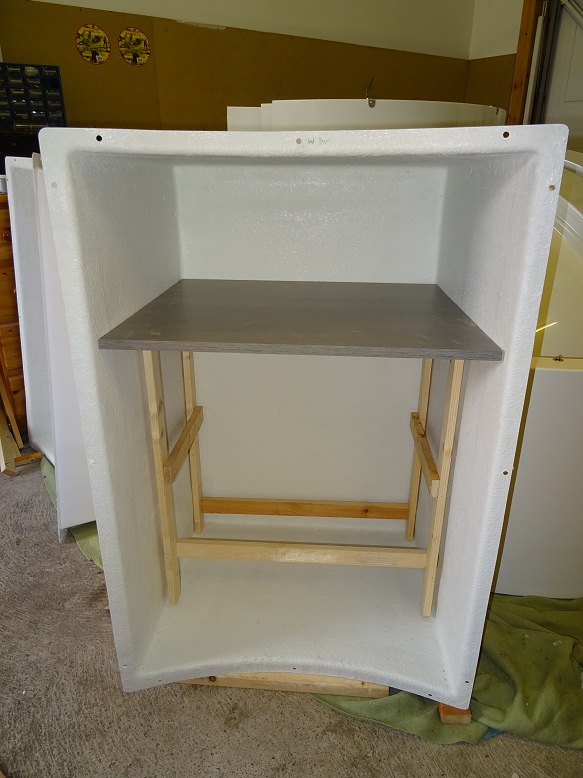
| Bay Cabinet Construction (2018-04-18) | ||
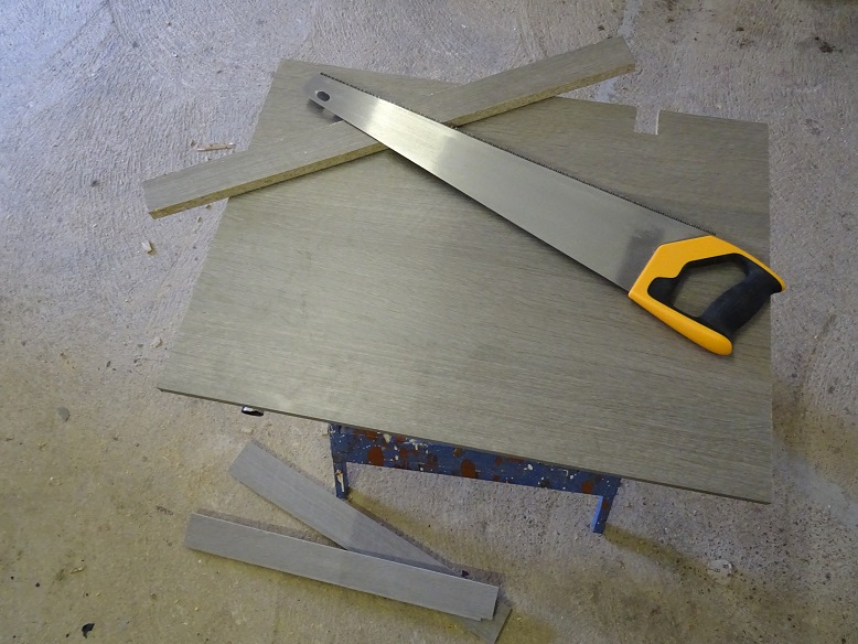
| Framework for one of the bay cabinet units started (Back legs need to be shorter than the front legs to allow for bay's geometry and obtain horizontal desktop. These were cut after dome had been assembled). |
Desk surface cut to size (desktop is wider at front than the rear to allow for bay's geometry) This cabinet is for main Power Panel and for AllSky/Weather monitoring |
|
 |
 |
|
Back to Top
| Dome Assembly | ||
| Dome Roof Quadrant, Wall Quadrants and 2 Bays - Ready to Start | ||
 |
||
| Dome Roof Quadrants, Concrete Pad | Assembling the Dome Roof | |
 |
 |
|
| Dome Roof Completed | Dome Roof Completed | |
 |
 |
|
| Assembling Dome Walls | Attaching Dome Walls to Concrete Pad | |
 |
 |
|
| Dome Walls Completed | Ready to Lift Dome Roof onto Base | |
 |
 |
|
| Fitting Observatory Bays (problem fitting central top bolt) |
Fitting Observatory Bays (solution to fitting central top bolt) |
|
 |
 |
|
| Observatory Door | Observatory Assembly Completed | |
 |
 |
|
Follow Up Note
One mistake I made during installation was not ensuring that the four walls quadrants formed a perfect circle before bolting everything in place. Whilst I ensured that the two diagonals across opposing quadrants were of equal in length at the quadrant centres I failed to recognise that the walls could still take on a slightly elliptical rather than circular shape. As a consequence the roof probably doesn’t move quite as smoothly as it should.
Back to Top
The Observatory Installation Guide
states "To give a pleasing finish to the observatory interior,
use matt black aerosol paint and carefully spray over dome top joins and
bolt any other interior marks". Since there were quite a few places
where the supplied black matt finish was incomplete causing bright
sunlight to show through or marks from dusty handmarks etc these were
sprayed over as well.
The
observatory outfitting phase suffered lengthy delays as a number of
different attempts where made to achieve an acceptable matt black finish to the
interior of the dome roof. It took 5 different aerosols/paints
before I found one that produced an acceptable finish.
1) I first used Matt Black Rust-Oleum aerosol paint for spraying over joins
and marks. Unfortunately the finish produced a satin and in places glossy finish rather than the
expected matt finish and it
contrasted strongly with the supplied matt black background, even
after thoroughy drying.
I took the empty aerosol can back to B&Q,
complained that the expected 'Perfect' Finish stated on the can was
not
perfect and got a full refund.
2) I painting over some of the
aerosol sprayed areas with some spare water based matt black paint. This was
better, but still left a noticeable
contrast with the supplied matt
black background. I didn't have enough of this paint to repaint
the entire interior.
3) I then bought and applied a tin of
Blackfriars Matt Black Paint (white spirit solvent). The finish was
again poor. Maybe the paint hadn't mixed or had thickend towards
the bottom of the can, but some parts had dried to a shiny like gloss. Even
the matt areas were somewhat patchy.
4) I then bought and applied a
tin of Johnstone's Matt Black Paint (again white spirit solvent).
The paint was very slow to dry and worried that overnight condensation
would affect the paint I left on upstanding light on in the observatory
overnight. The result was that the areas of the dome
interior in shadow dried with a matt finish, whilst the areas in direct
light dried with a gloss finish ! . Same paint / same application.
5) It wasn't until I bought and applied a tin of Delux Matt Black
Emulsion (water solvent) that I finally got a finish that I was content
with.
| Dome Roof Interior - after 'touching up' with matt black aerosol spray paint (2018-04-21) | ||
| Roof Interior - after using Matt Black Aerosol (without flash) |
Roof Interior - after using Matt Black Aerosol (with flash) |
|
 |
 |
|
| Roof Interior - after using Matt Black Aerosol (definately not a pleasing finish) |
||
 |
||
| Dome Roof Interior - attempted repaint job with Johnstone's Matt Black Paint (2018-04-29) | ||
| Roof Interior - attempted repaint (paint taking a very long time to dry, and a upward pointing light was left on in observatory overnight to prevent condensation forming on the still wet paint, result was that shadow zone (bottom) dried with a matt finish , whilst the lit zone (top) dried with a gloss finish - same paint/same application ! |
Roof Interior - attempted repaint (patchy finish) |
|
 |
 |
|
| Roof Interior - attempted repaint (patchy finish) |
Roof Interior - attempted repaint (patchy finish) |
|
 |
 |
|
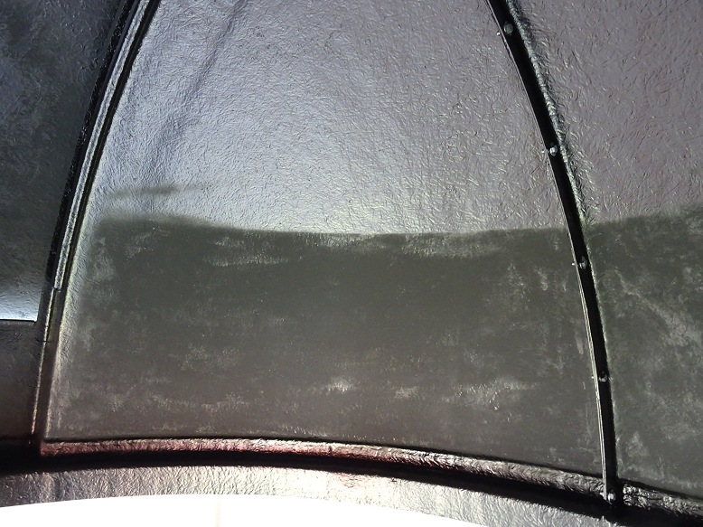
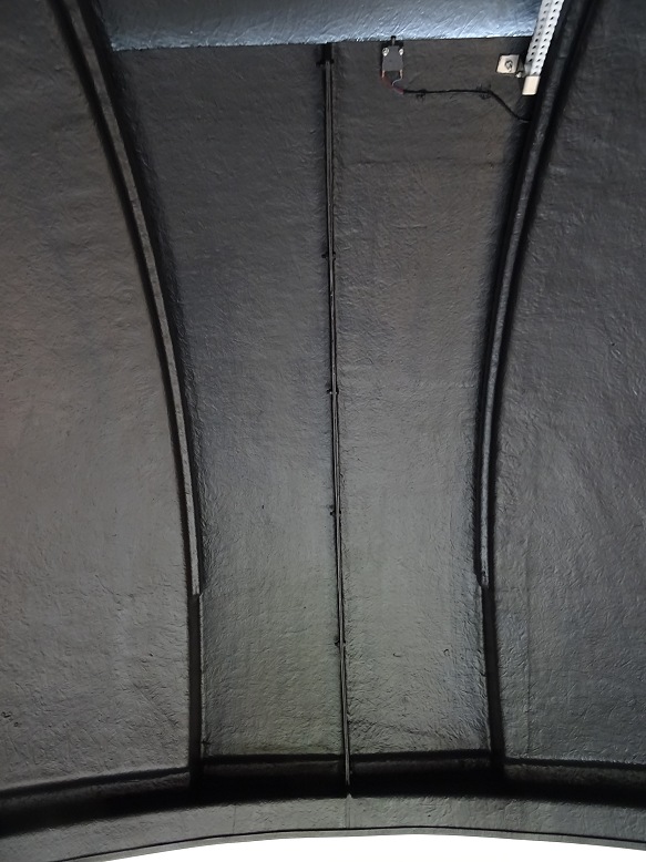
| Dome Roof Interior - Final Paint Job with Delux Matt Black Emulsion (2018-05-01) | ||
| Roof Interior - final finish (after remedial painting with Dulux black matt emulsion) |
Roof Interior - final finish | |
 |
 |
|
| Roof Interior - final finish | Roof Interior - final finish | |
 |
 |
|
Back to Top
Pictures below show the outfitting of the new dome observatory. The pictures have been arranged in a logical order but the subject groups are not necessarily presented in the exact order that equipment was built and/or installed. The outfitting phase was stretched out due to issues with achieving an acceptable dome roof interior.
Outfitting comprised
- Dome Clamps
-
Pier (including
Top Plate &
Wedge)
- Flooring
-
Telescope
- Bay
Cabinets
- Observatory Power (including
Bay to Bay conduits)
-
Dome Rotation Drive & Controller
(including Induction Charger)
-
Cabling & Telescope Accessories
-
AllSky Camera/Cloud Sensor Mast
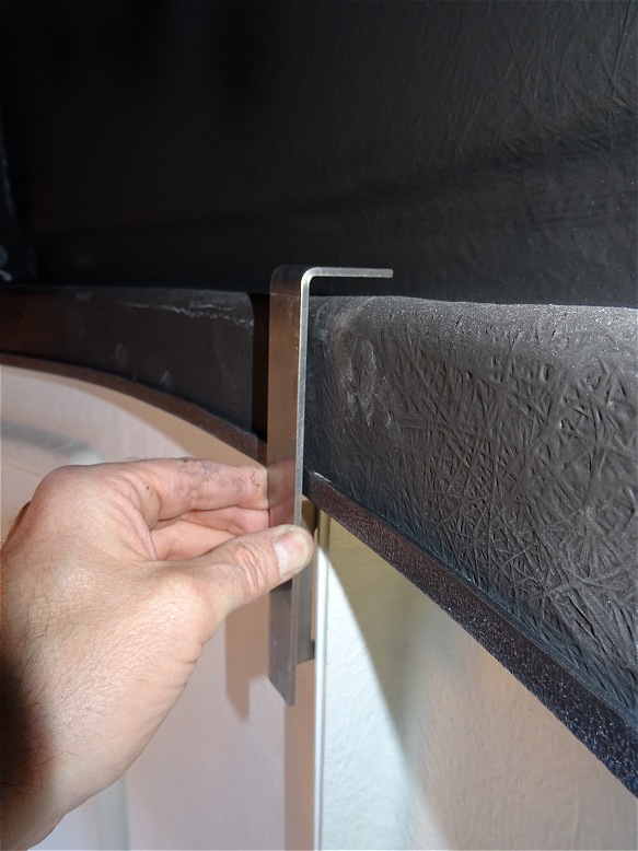
Dome Clamps (2018-04-20) |
||
| Dome Clamps (one of four dome clamps that are designed to provide a permanent in-place security to prevent the dome roof from lifting in strong wind or from being removed ) |
Dome Clamps - Fitting Issue Unfortuantely there was a problem with the clamps I was initially supplied with as the slots for taking the retaining bolts didn't align with the wall flanges. (replacement clamps were eventually recieved from Pulsar Observatories and installed on 2018-10-03) |
|
 |
 |
|
|
|
||
Shutter Drive (2018-04-21) |
||
| Shutter Drive - initial installation (Note: cable to motors should be inserted into base of shutter unit before attaching drive unit to observatory roof, it can't be inserted with unit attached !) |
Attaching Drive Motor Cable (cable is impossible to retrospectively attach with the drive unit already attached to the dome roof) |
|
 |
 |
|
| Drive Motor Cable finally attached (Note: cable attached after taking Shutter Drive Unit off the Roof, notice how cable has to be bent sharply to get it to attach) |
Shutter Drive Cable (show cable passing through pulley and its attachment to shutter) |
|
 |
 |
|
| Dome Roof Flange (Roof flange filed to ensure that it doesn't interfer with the passage of the dome drive chain) |
Shutter Drive Chain | |
 |
 |
|
| Shutter Drive Unit | Shutter Upper Stop | |
 |
 |
|
|
|
||
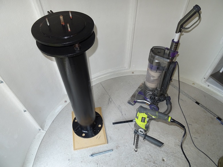
Pier Installation (2018-04-28 to
2018-05-02)
|
||
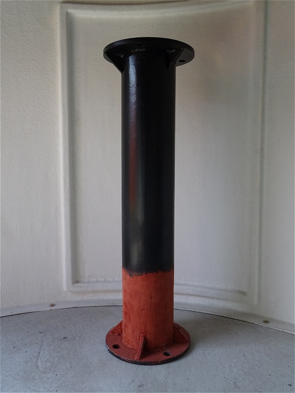
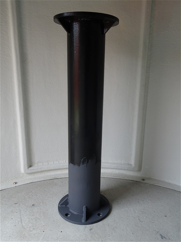
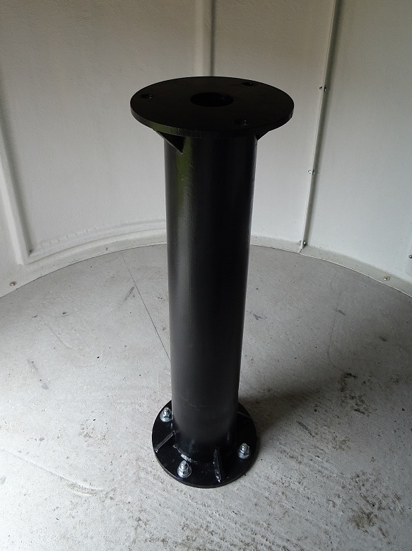
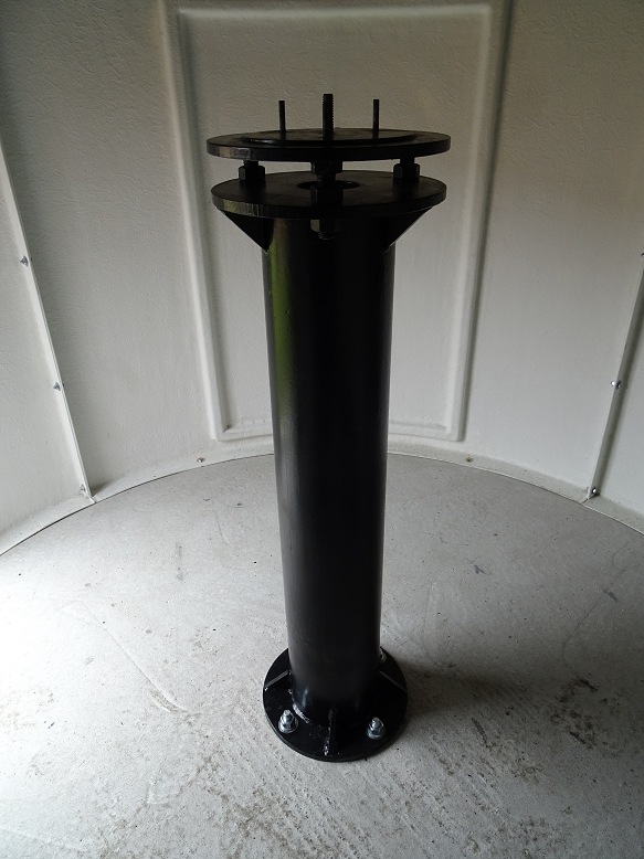
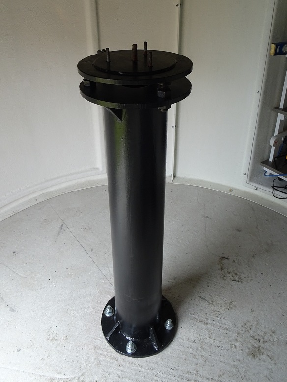
| Shortened Pier (Pier after being shortened to a new height of 93cm by a local fabrication workshop) (see original pre-shortened pier) |
Pier with grey primer (black satin paint failed to attach directly to red-oxide on first paint attempt, requiring the red-oxide to be rubbed and over painted with a grey primer before reapplying black top coat) |
|
 |
 |
|
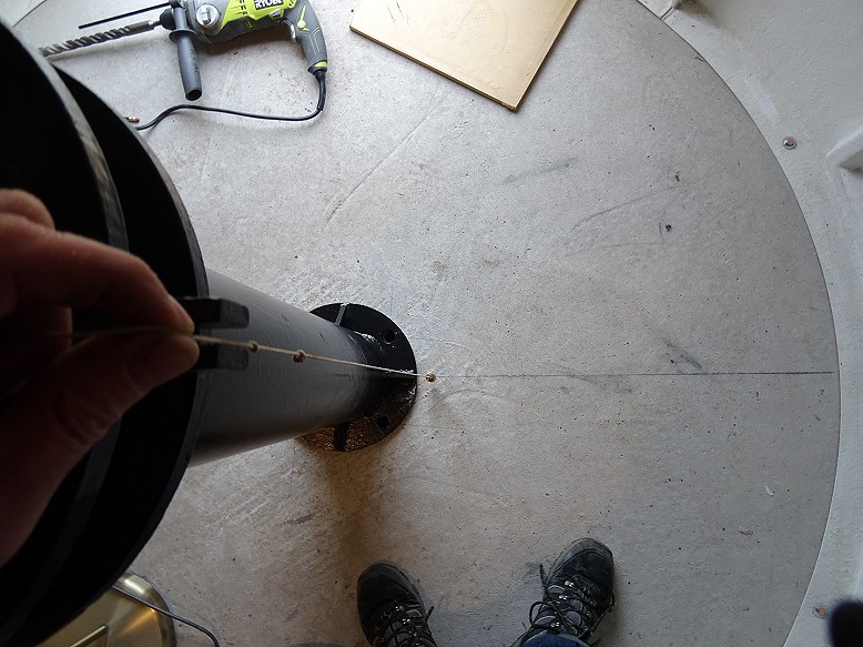
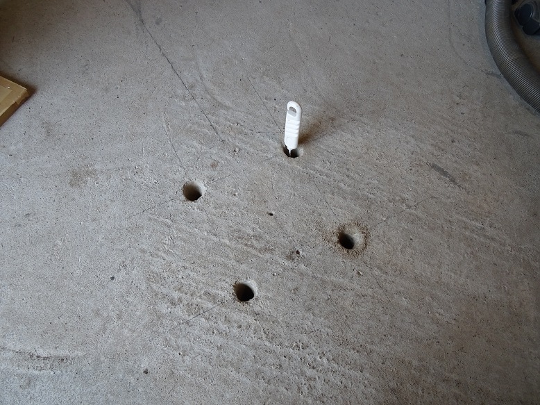
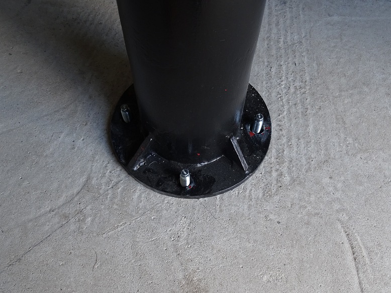
| Aligning Pier with earlier N-S line (pier laid over a scribed circle centred on planned pier position, and rotated so that south side of pier is precisely aligned with earlier N-S alignment line, centre of 4 pier holes then scribed on concrete floor) |
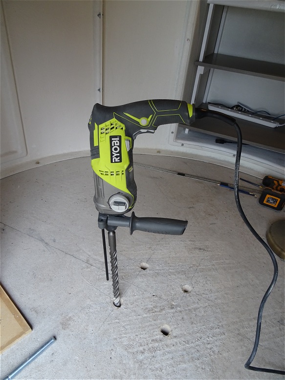
Preparing Holes for Pier Bolts (pier, SDS drill, studs, vacum Cleaner) |
|
 |
 |
|
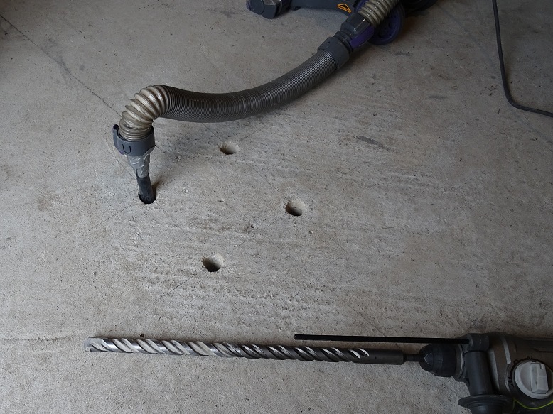
| Drilling holes with SDS drill & 22mm masonary bit (holes were piloted with a smaller bit beforehand) |
Cleaning hole of debris with homemade vaccum attachment |
|
 |
 |
|
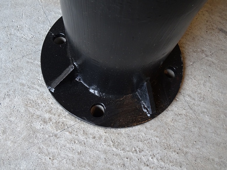
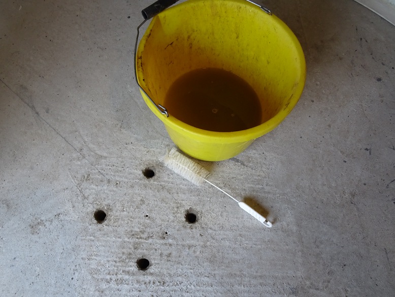
| Checking Pier Holes with Pier Base | Cleaning sides of hole with dry brush | |
 |
|
|
| Cleaning hole with dry brush | Cleaning hole with wet brush | |
 |
 |
|
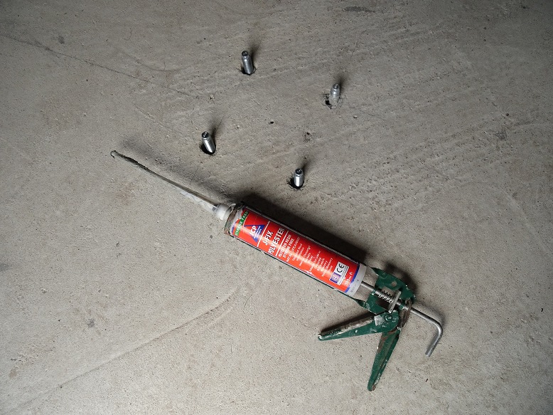
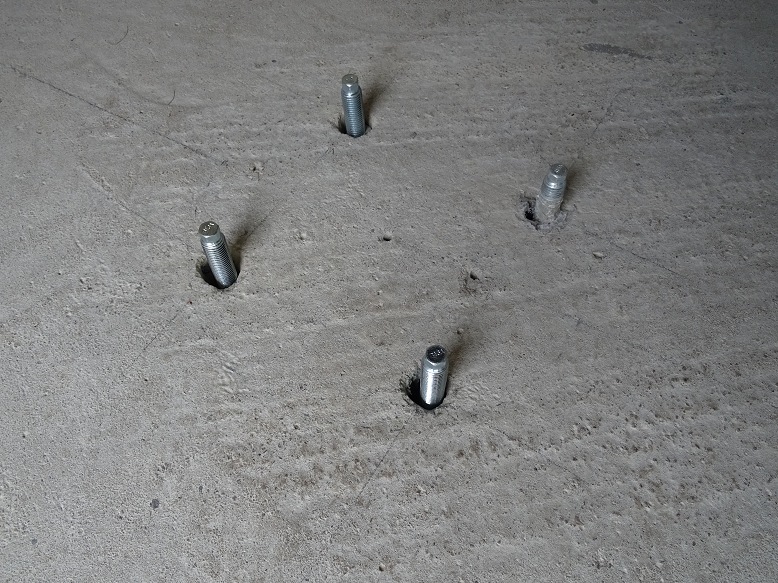
| Pier studs with used tube of J-Fix Polyester Resin | Pier studs in place | |
 |
 |
|
| Waiting for resin to firmly set before locking down nuts | ||
 |
||
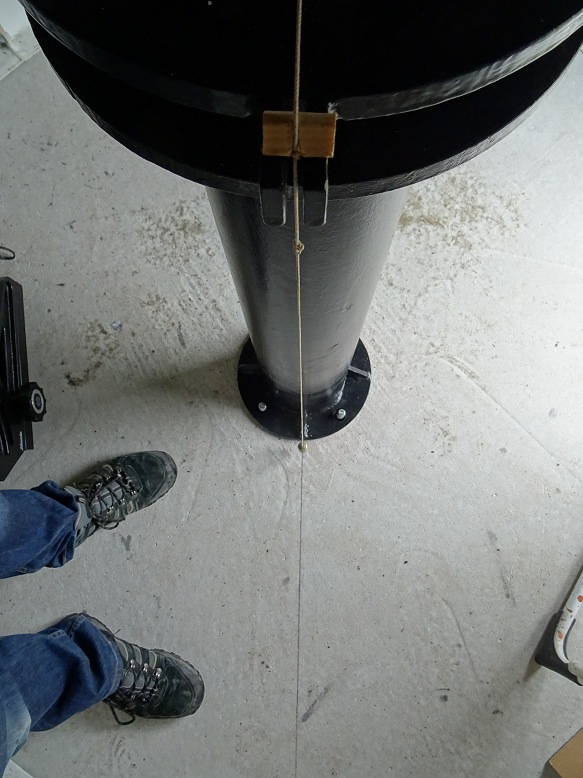
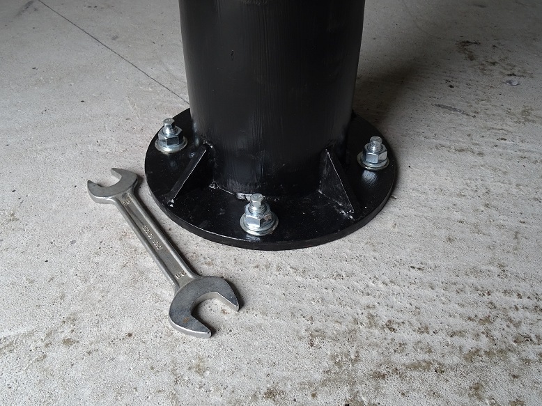
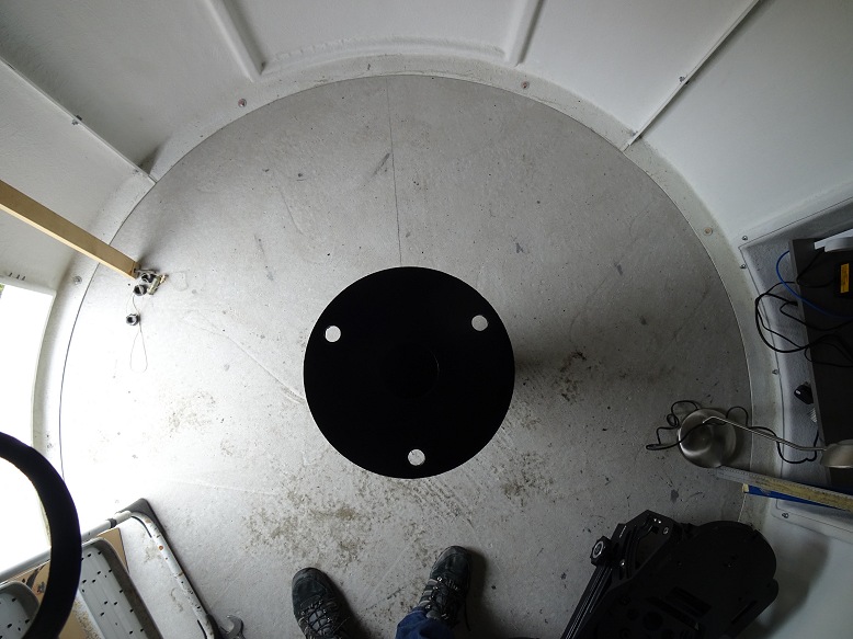
| Final Pier Alignment Check (checking that Pier will be aligned with earlier N-S Alignment Line before bolting it down) |
Pier Installed | |
 |
 |
|
| Final Pier Alignment Check (checking that Pier will be aligned with earlier N-S Alignment Line before bolting it down) |
Pier Installed (top view) | |
 |
 |
|
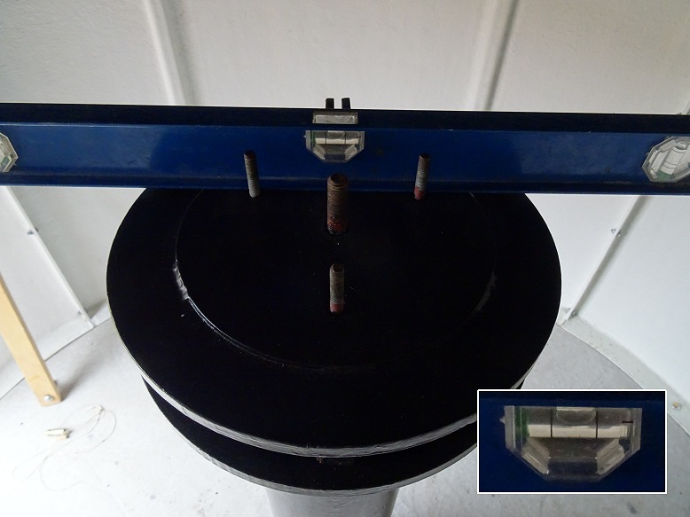
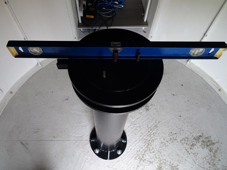
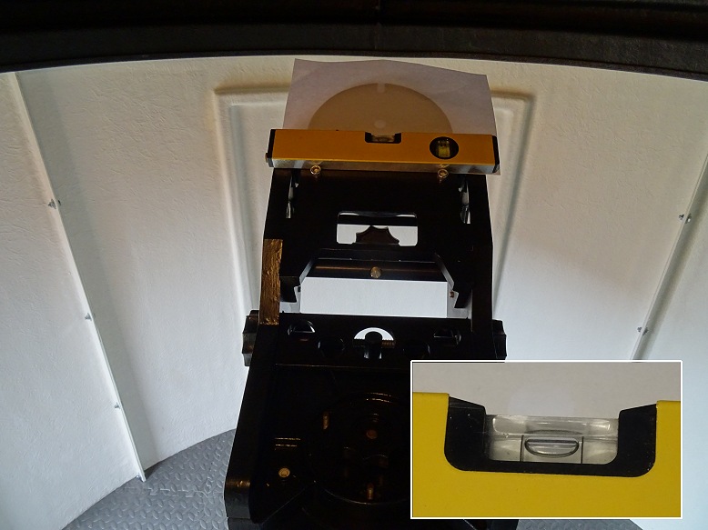
| Installing Top Plate (checking that Top Plate is horizontal in the E-W direction) |
Installing Top Plate (checking that Top Plate is horizontal in the N-S direction, this direction is less important as any discrepencies in that direction can be corrected when adjusting the wedge inclination during polar alignment) |
|
 |
 |
|
| Top Plate Installed | Top Plate Installed | |
 |
 |
|
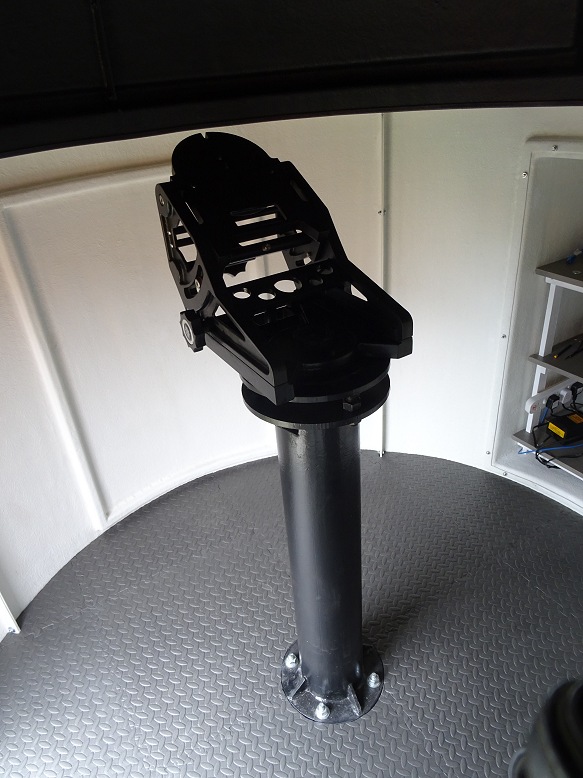
| Checking that wedge is horizontal in E-W direction | Wedge Installed On Pier | |
 |
 |
|
|
|
||
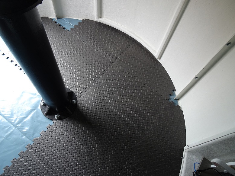
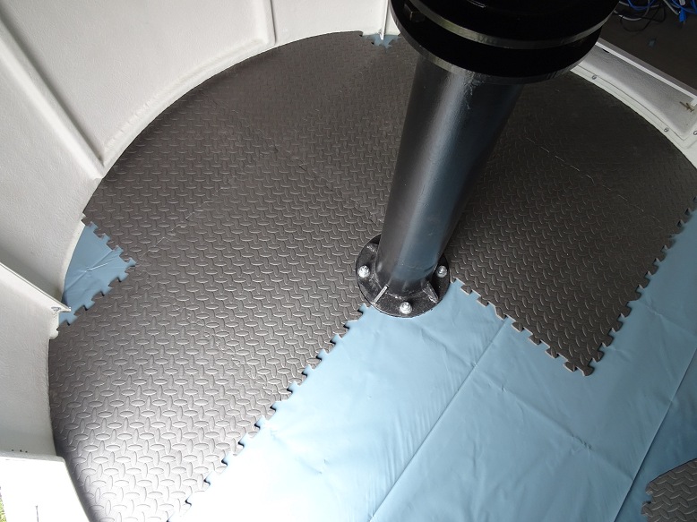
Flooring Installation (2018-05-02) |
||
| Damp Proof Membrane (membrane cut prior to dome assembly) |
Interlocking Floor Mats (mats cut prior to dome assembly) centre is disorted in picture due to image perspective |
|
|
|
|
|
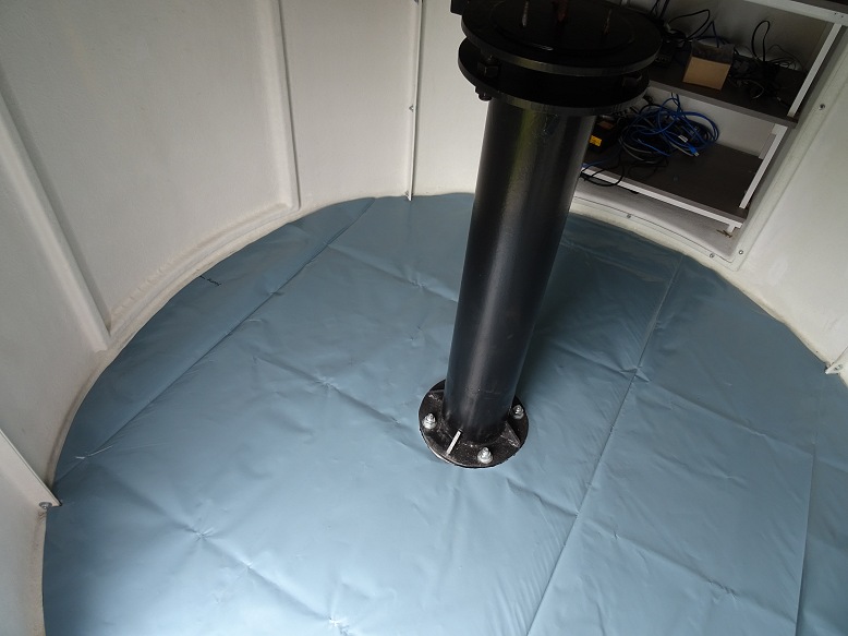
| Damp Proof Membrane Installed | Installing Interlocking Floor Mats | |
 |
 |
|
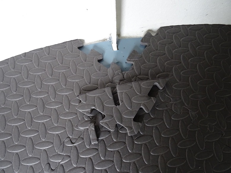
| Installing Interlocking Floor Mats |
Cutting slots for the wall flanges (these 4 corner mats were left to last) |
|
 |
 |
|
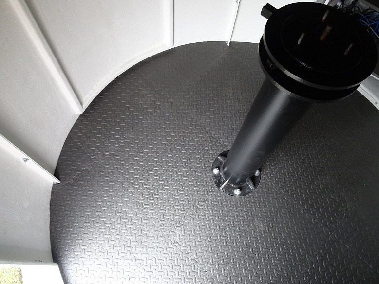
| Floor Mats Installed | Floor Mats Installed (top view) | |
 |
 |
|
|
|
||
Telescope Installation (2018-05-02) |
||
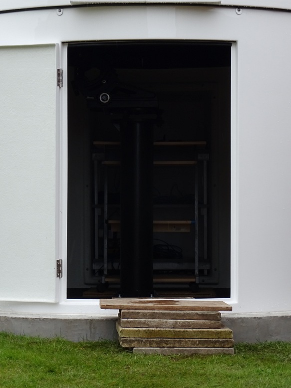
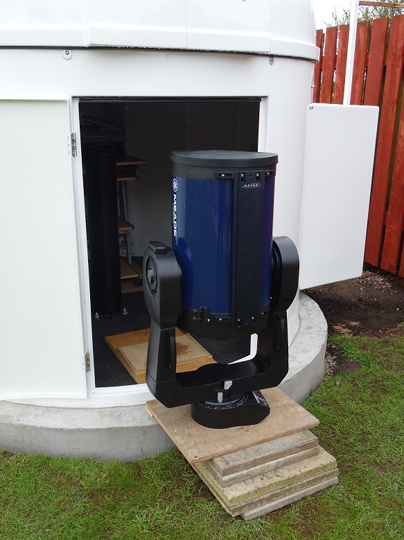
| Temporary platform (platform built to aid entry of heavy 12" LX200 into dome) |
12" LX200 about to enter observatory | |
 |
 |
|
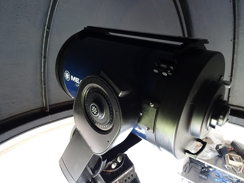
| LX200 telescope installed in dome | LX200 telescope installed in dome | |
 |
 |
|
|
|
||
Bay Cabinet Installation |
||
| Cabinet in Bay 1 (Power Panel & AllSky/Weather Monitoring) Desktop later reduced from 54cm to 48cm depth to prevent water of condensation dripping from roof interior |
Cabinet in Bay 2 (Telescope / Observatory Control) Desktop & lower shelf later reduced from 55cm to 48cm depth |
|
 |
 |
|
| Cabinet in Bay 2 (Telescope / Observatory Control) Picture shows cabinet after reducing Desktop/Shelf Depth and after fitting leads to telescope |
Cabinet in Bay 2 (Desktop for Telescope / Observatory Control) Power Lead, Ethernet Cable & USB3 cable for ASI ZWO camera on left, USB cable to Hub and Mouse on right) |
|
|
|
 |
|
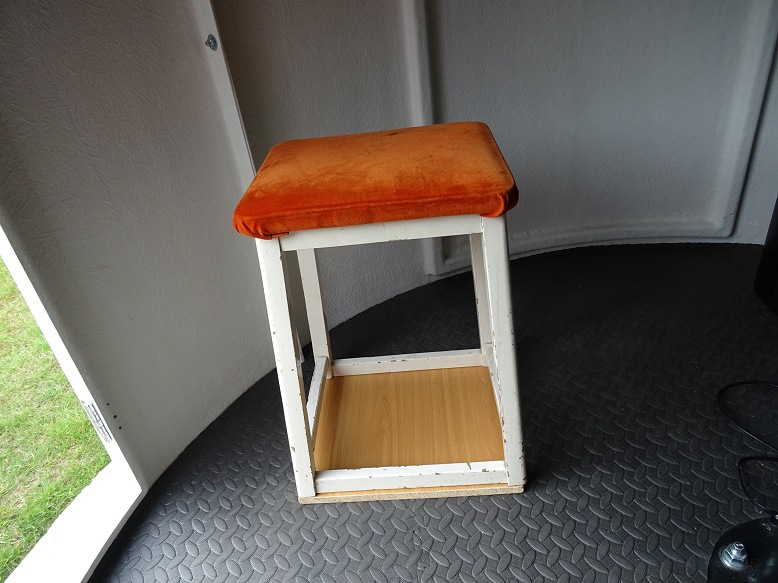
| Observatory Stool (Stool taken from old observatory and modified to reduce its height to make it suitable for working at the height of the cabinet desktops and to add a flat base to avoid leg indents on the interlocking rubberised floor mats) |
||
 |
||
|
|
||
Observatory Power Installation (2018-04-21) |
||
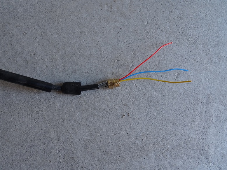
| Existing SWA Power Cable realigned for new observatory (excess cable would be cut later and the cable taken up through the base of one of the bays) |
Preparing SWA Cable for tie-in (cable taken up through a 20mm conduit in base of Bay 1) |
|
|
|
 |
|
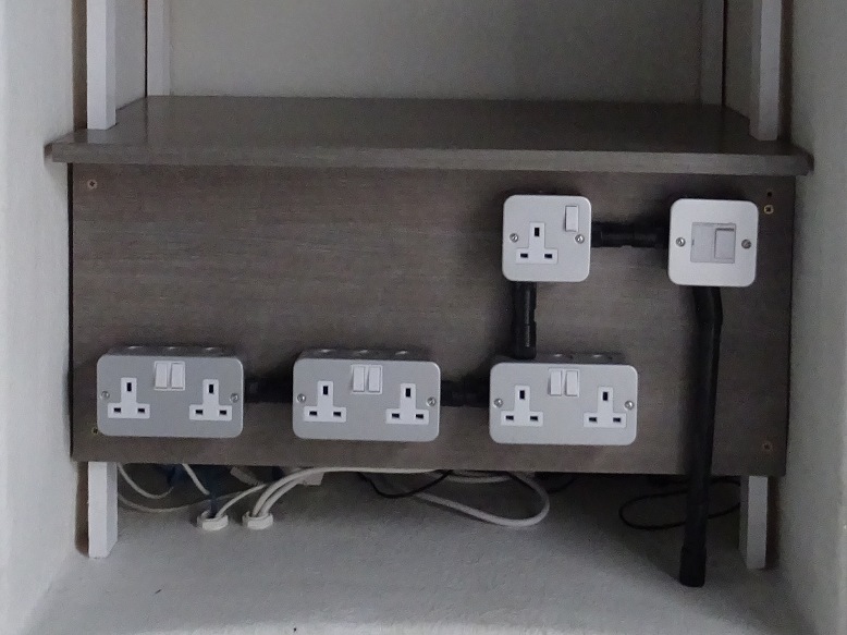
| Power Panel under Cabinet in Bay 1 (7 sockets compared to 5 sockets in original design) |
SWA Cable hooked up to Power Panel (note a RCD is located at the house end of the SWA Cable) |
|
 |
 |
|
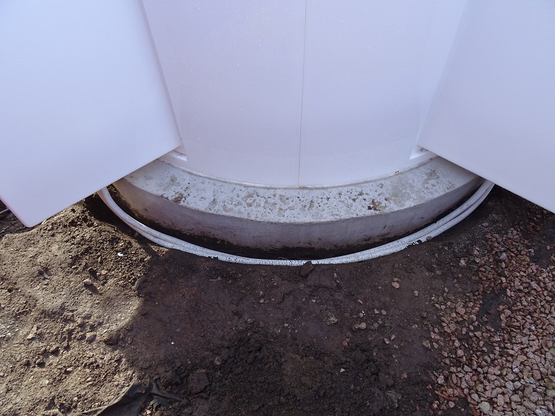
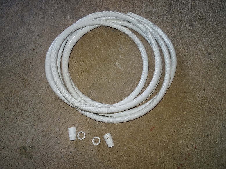
| Power and Data Conduits between Bays (2018-04-25) | ||
| Flexible Conduits travelling between two bays One conduit carries power from Power Panel Bay (left) to Telescope Bay (right). The second conduit carries Ethernet cable and plus a USB cable for operating the Dome Drive. |
Flexible Conduit for taking Power & Data (25mm flexible conduit and glands) |
|
 |
 |
|
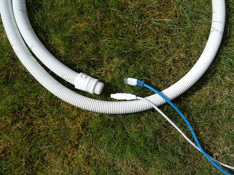
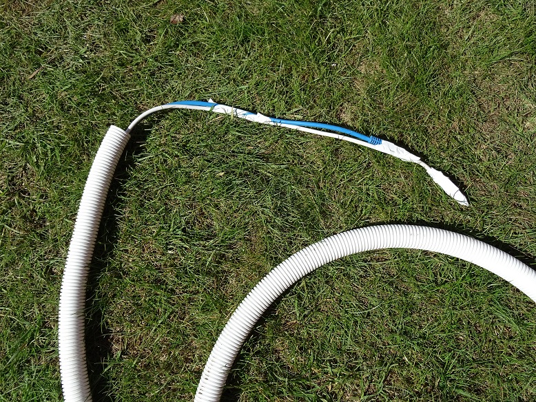
| Data Cables about to be inserted into Flexible Conduit (1 USB, 1 Ethernet) (lug on ethernet connection is held down with tape to prevent it sticking in the conduit) |
Data Cables emerging from end of conduit (tape has had to be used to cover over sharp or square edges on the two connnectors, tape also had to be used to increase the rigidity of the inserted cables and enable the cables to be pushed through to the end) |
|
 |
 |
|
| Cabinet in Bay 2 (Telescope Control Bay) Picture taken after running power/data cables from Bay 1, but before fitting shelves and desktop |
Power Cables & Data Cables emerging from conduits (Telescope Control Bay) |
|
 |
 |
|
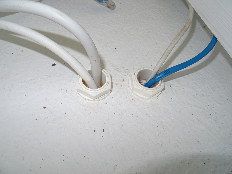
| Cables emerging from 25mm conduits at bottom of bay 2 |
Power Cables & Data Cables emerging from conduits (Power Panel/AllSky Camera Control Bay) |
|
 |
|
|
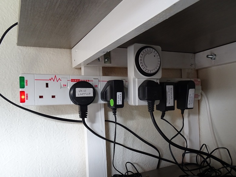
| Power Strip under cabinet in Bay 1 (AllSky Camera & Weather) |
Power Strip under cabinet in Bay 2 (Telescope/Observatory Control) |
|
 |
 |
|
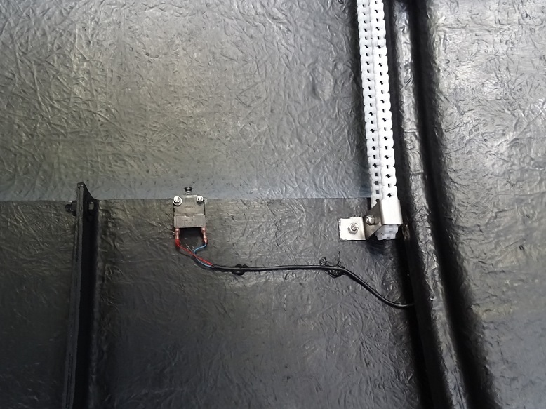
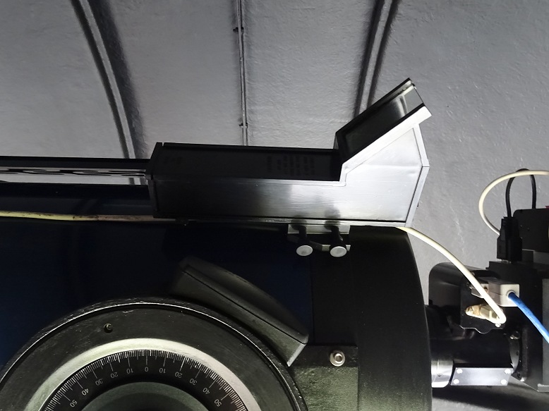
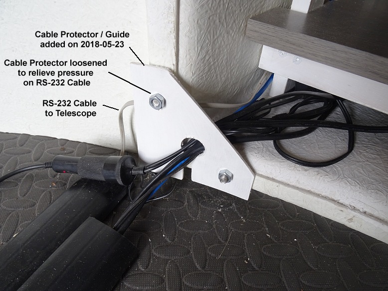
| Cable Protector/Guide Addition of protector on 2018-05-23 may have been responsible for a series of Telescope Communication Errors seen during the next two sessions by pressing too tightly on RS232 Cable to the Scope (this was later fixed by relieving the pressure on cable) |
||
 |
||
| Observatory Lights (2018-05-07) | ||
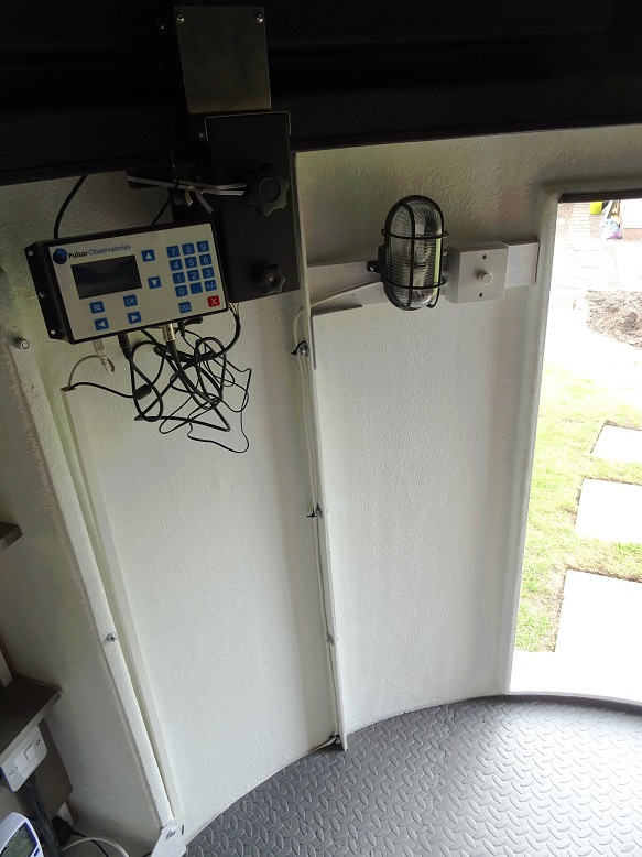
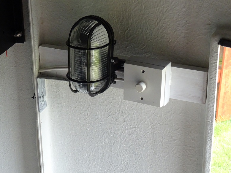
| Light & Light Switch (with dimmer) next to door |
Light & Light Switch (with dimmer) | |
 |
 |
|
|
|
||
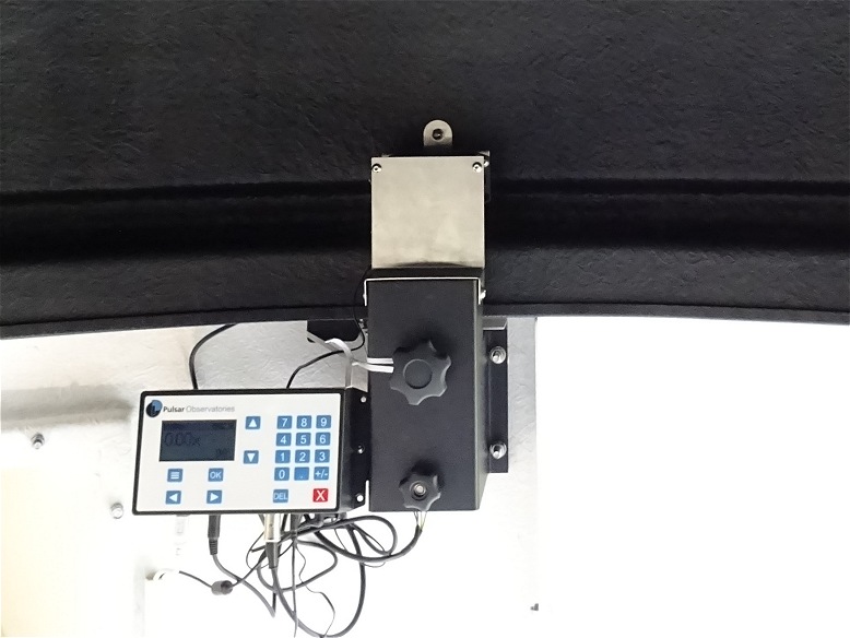
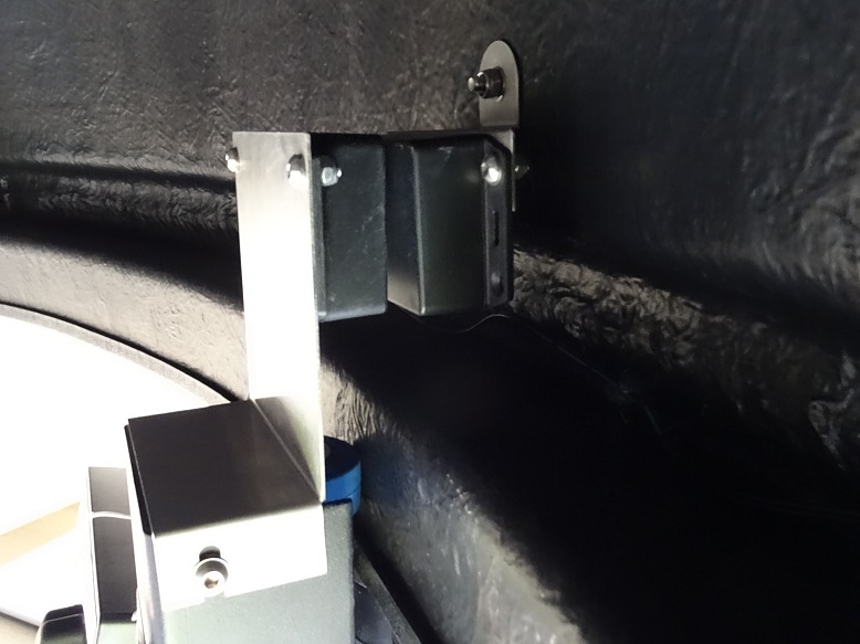
Dome Rotation Drive & Controller (2020-04-29) |
||
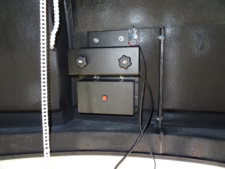
| Rotation Drive & Control Panel (unit prior to installing) |
Rotation Drive Wheels (blue) & Encoder Wheel (grey) (unit prior to installing) |
|
|
|
|
|
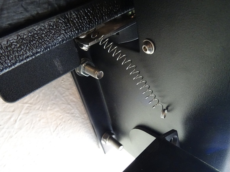
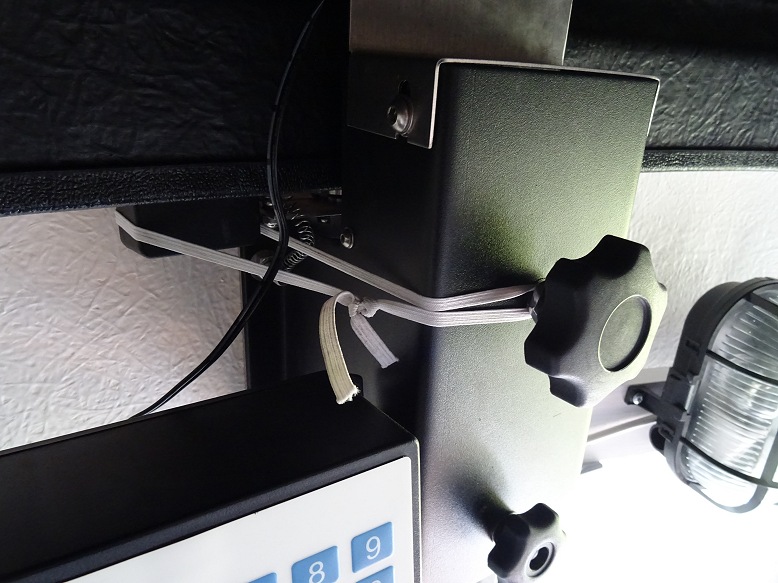
| Over-stretched Spring on encoder arm (spring on encoder arm that became irrepairably overstretched when front motor / driver controller was removed from back motor plate without unhooking the spring) |
Temporary Workaround / 'Bush Fix' (elastic loop wrapped around encoder block to keep encoder wheel tensioned against the roof flange) |
|
 |
 |
|
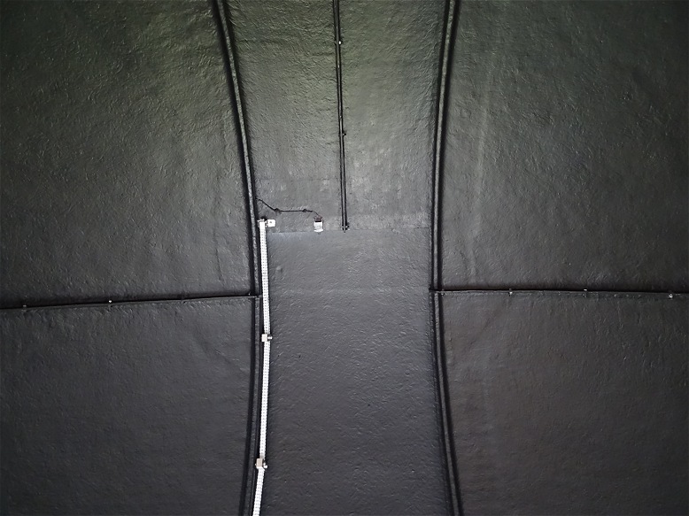
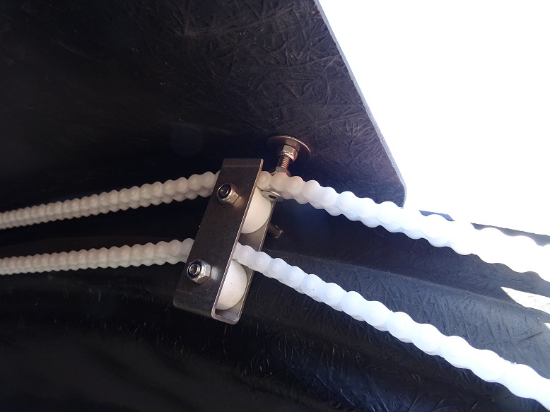
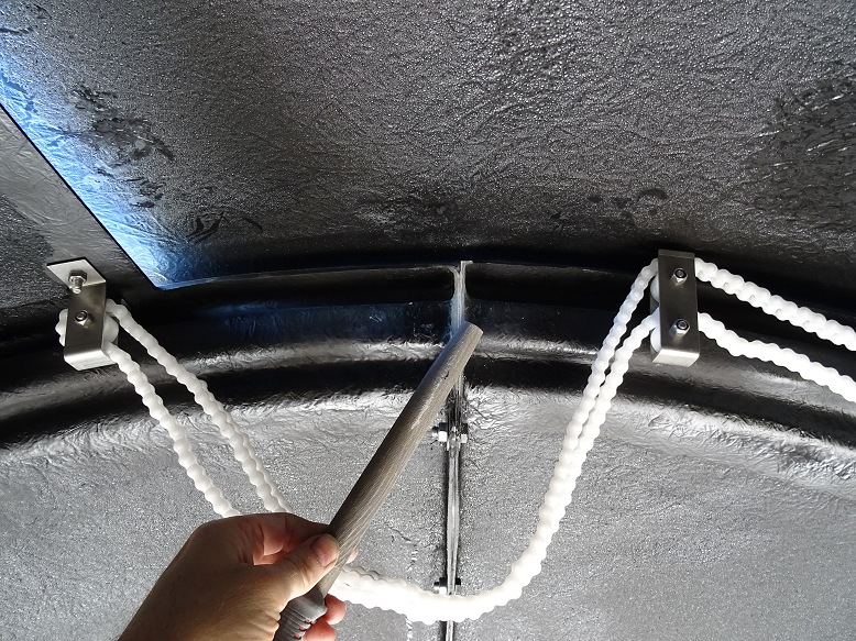
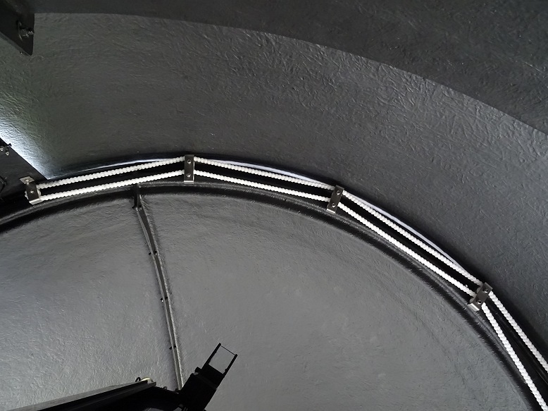
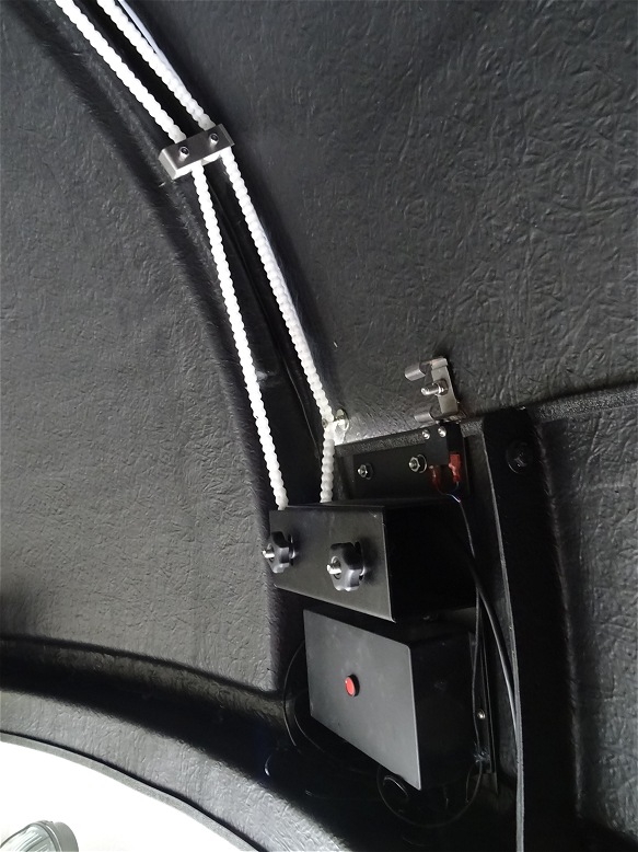
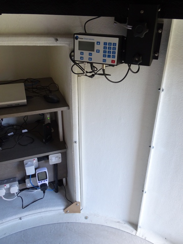
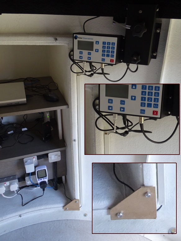
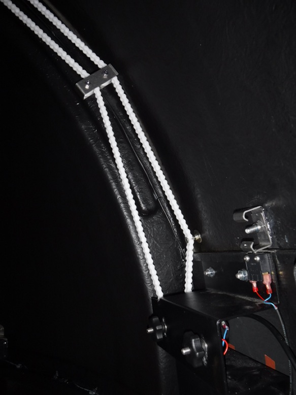
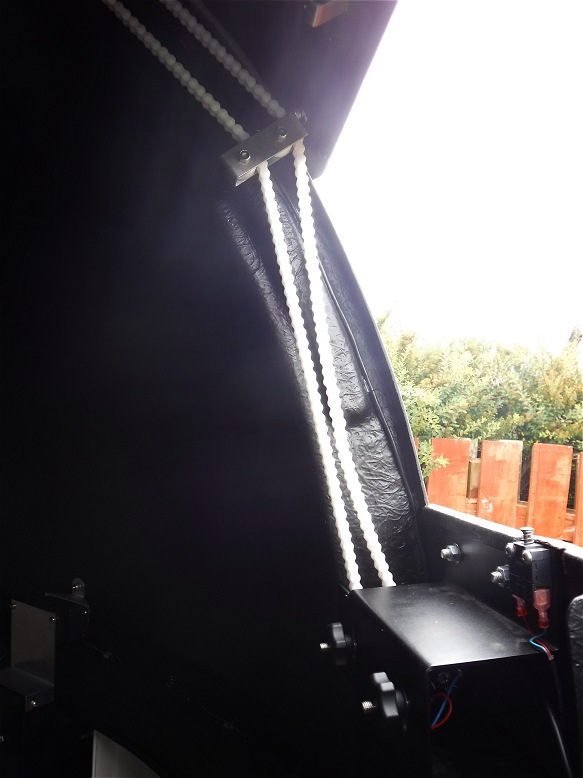
| Conduit for 12V Power Cable & USB Cable to Dome Drive Controller (2020-04-29) | ||
| White conduit taking 12V power line & USB control cable | Picture showing detailed view of top and bottoms of conduit | |
 |
 |
|
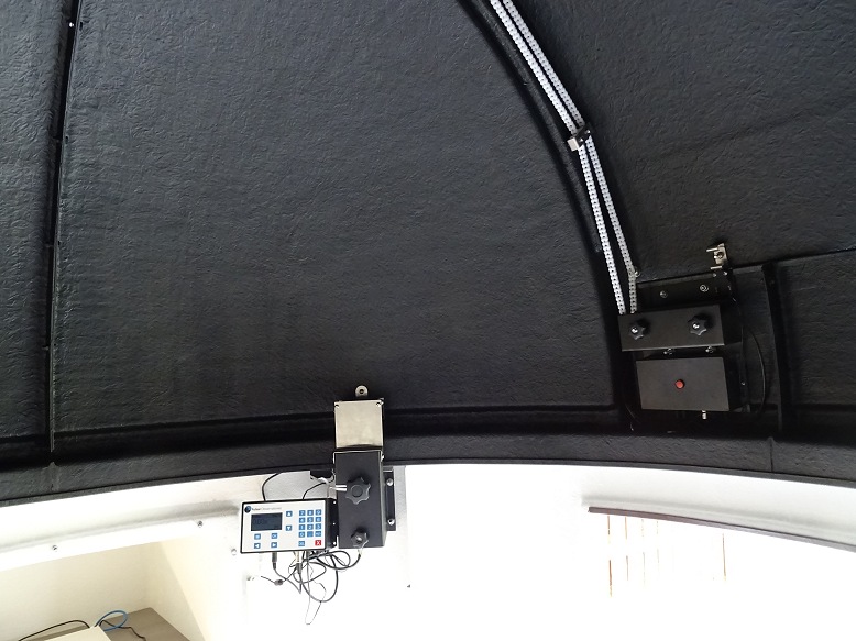
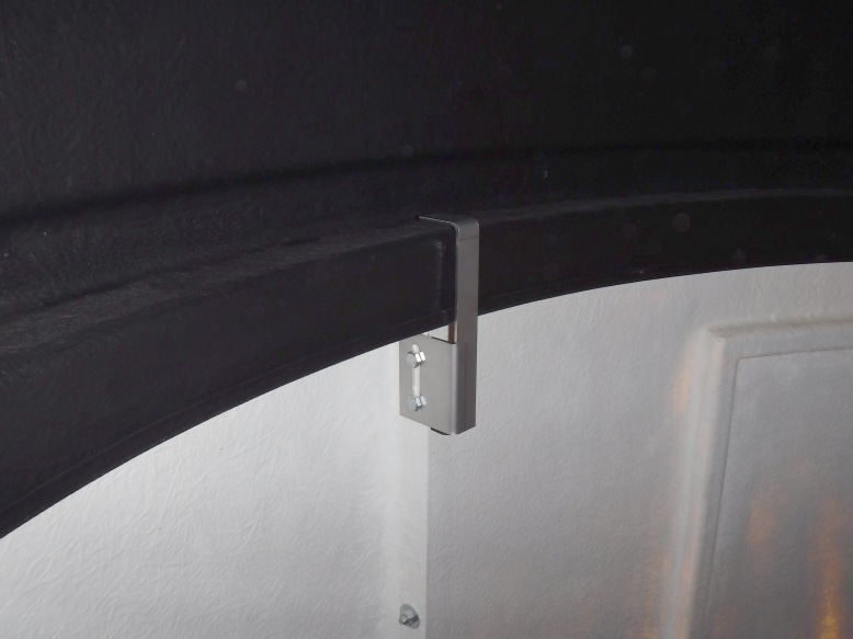
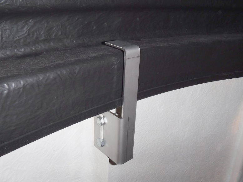
| Induction Charger (2018-05-02) | ||
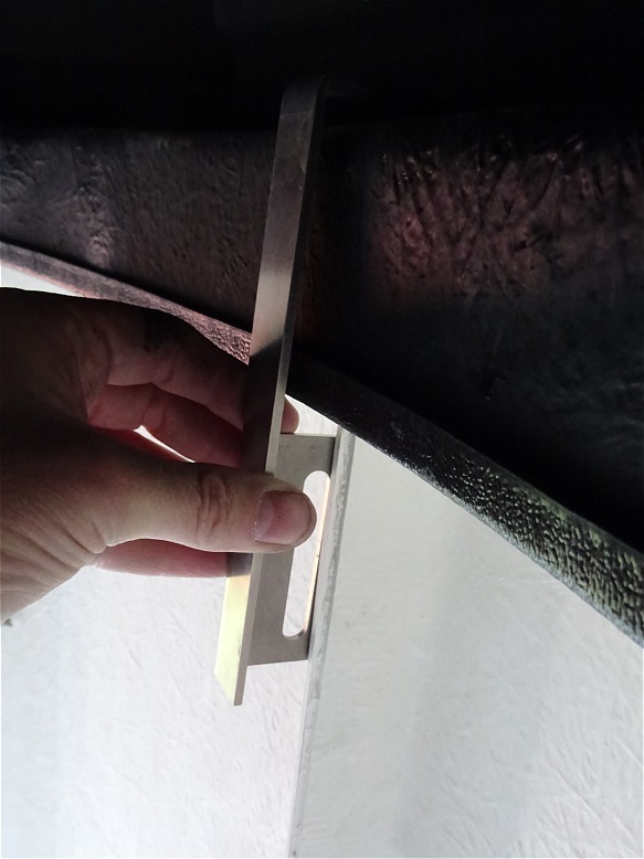
| Induction Charger - front view (installed above Rotation Drive, charges the shutter drive in the roof using induction, no direct leads !) |
Induction Charger - side view (gaps ranges from 8 to 10mm) |
|
 |
 |
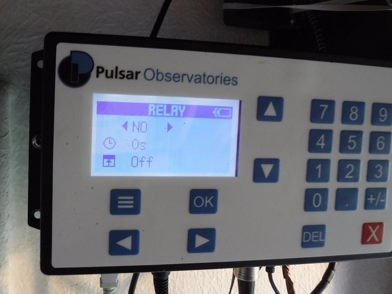
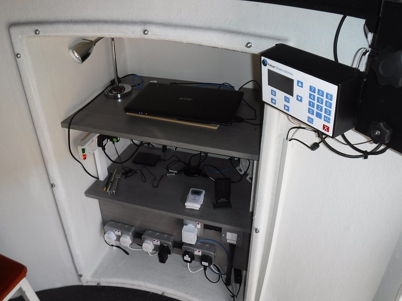
|
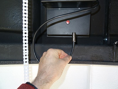
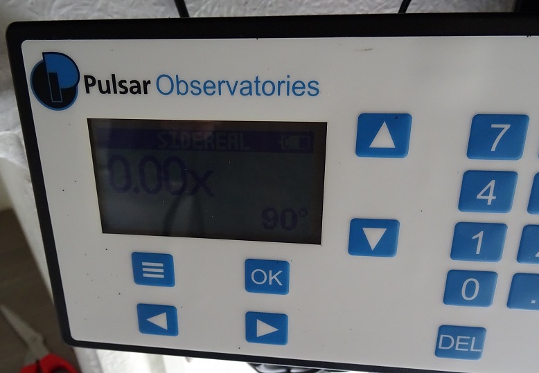
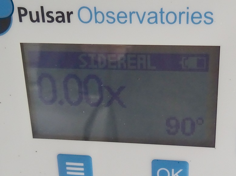
| Dome Controller | Dome Controller - LCD screen (showing shutter battery status) |
|
 |
 |
|
|
|
||
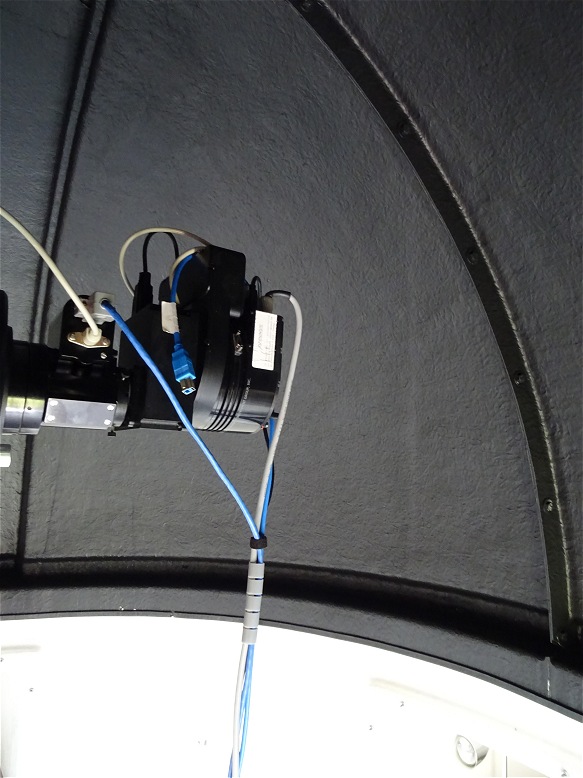
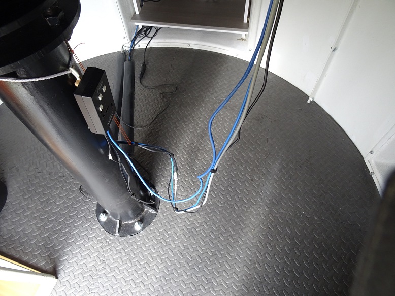
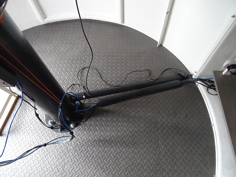
Cabling and Telescope Accessories (2018-05-07) |
||
| Optec-TCF-S focuser & ST-10 Camera connected to Scope. USB 3 cable is for ASI ZWO camera (not yet attached) |
Cables to/from Telescope (Optec TCF-S controller box mounted on pier) |
|
 |
 |
|
| Cables to/from Telescope (orange string is a trial attempt to carry weight of cables from back of scope and stop them dragging across the floor) |
Cables to/from Cabinet in Bay 2 |
|
 |
 |
|
| Telrad attached to dovetail & 12" LX200GPS Telrad has been screwed to a male dovetail, taken from Meade finder scope that is not used, to provide a more secure attachment than the normal sticky pad attachments |
||
 |
||
|
|
||
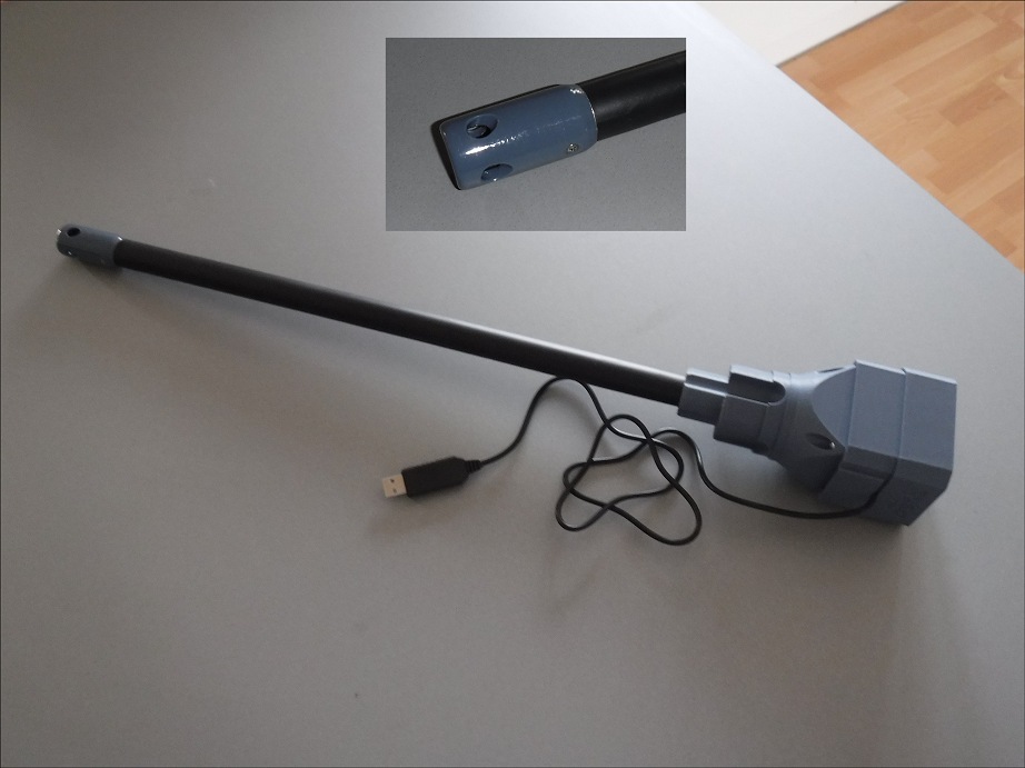
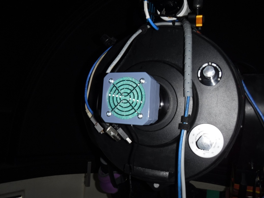
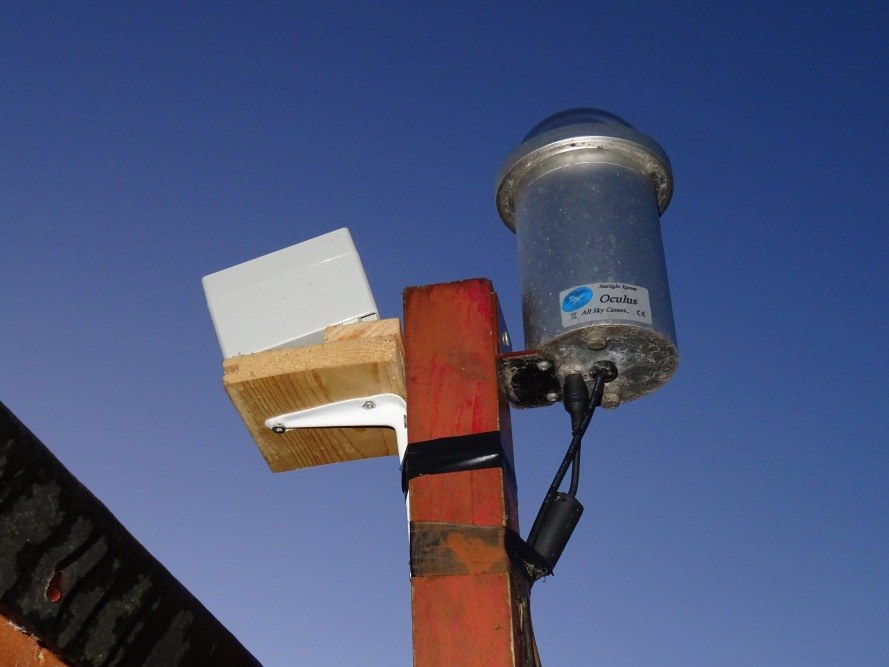
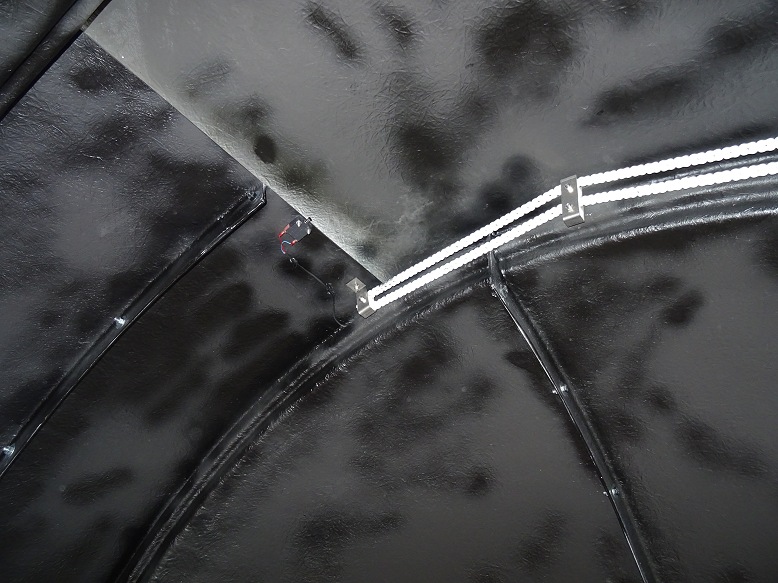
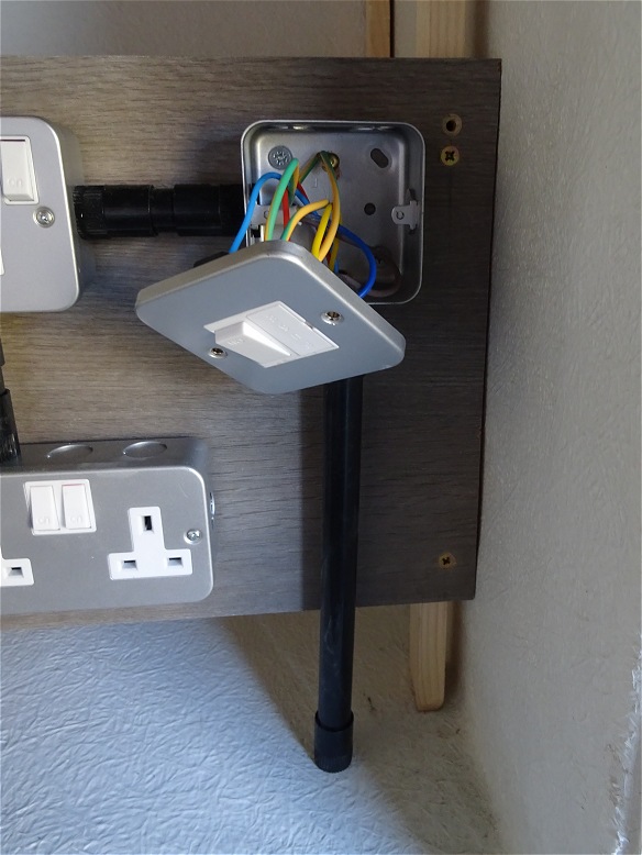
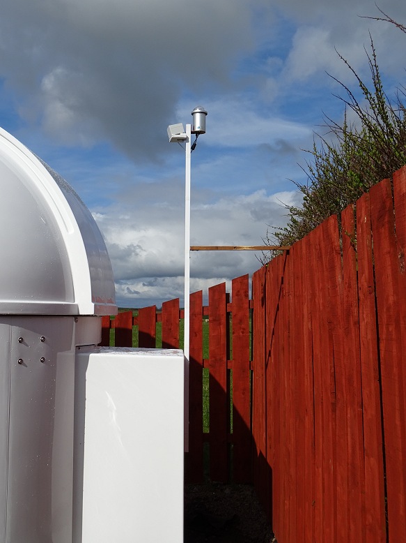
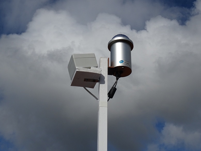
AllSky Camera/Cloud Sensor Mast (2018-04-29) |
||
| AllSky Camera & Cloud Sensor Mast (mounted on mast on the north side of the Dome) |
AllSky Camera / Cloud Sensor Closeup | |
 |
 |
|
| AllSky Camera (Camera poking above the observatory roofline, camera is mounted on mast on the north side of the Dome) |
AllSky Camera Closeup | |
 |
 |
|
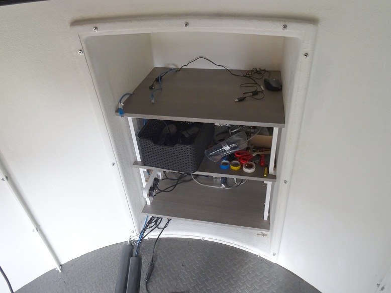
| Associated AllSky/Weather Accessories in Cabinet in Bay 1 (top down view, prior to fitting desktop, showing Powerstrip with plugs/adapters (left), USB Hub & USB Hard Drive (centre), LAN Hub & Weather Station USB Hub (right) ) |
||
 |
||
|
|
||
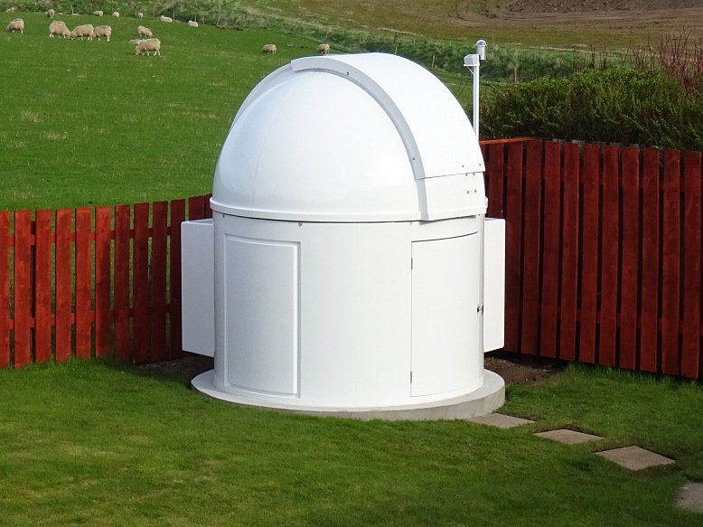
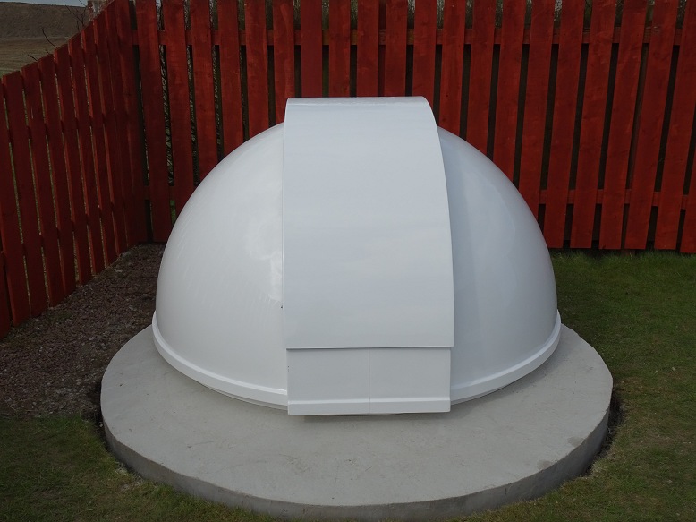
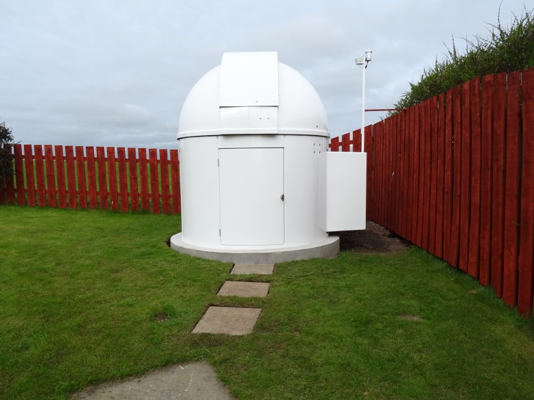
Completed Observatory (2018-05-07) |
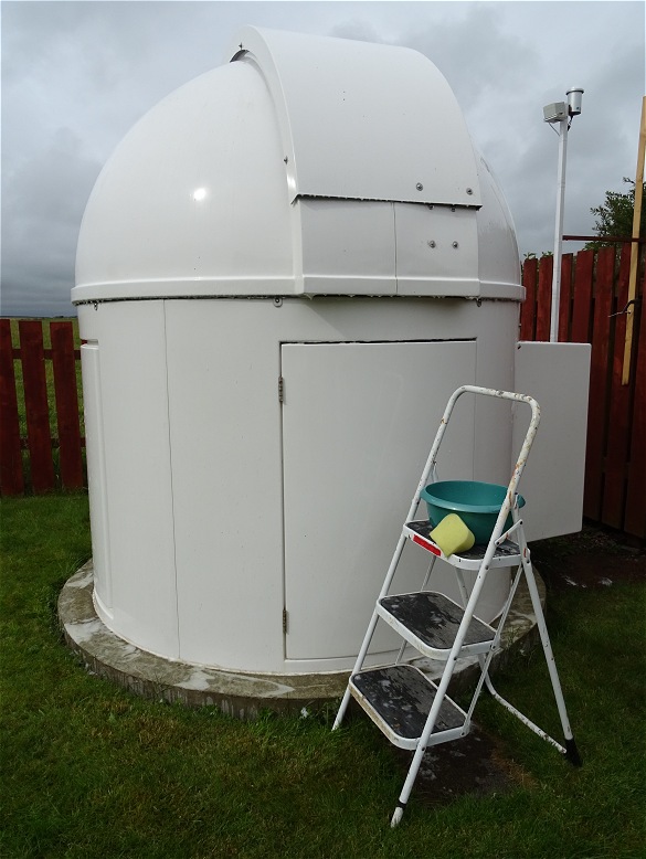
||
| Completed Observatory | Completed Observatory | |
 |
|
|
Back to Top
Aims for the commissioning phase:
- Identify and rectify issues relating to
the design, assembly and kitting out of the
observatory
- Configure POTH.Hub for operating LX200
Scope and Pulsar Dome together
- Identify any issues relating to the
Dome Controller
- Test
observatory control software (identify/fix any bugs,
identity/prioritise any useful enhancements)
- Set up main scope (Telrad
Alignment, Polar
Alignment, Periodic Error Testing & Correction, Telescope Balance)
- Log
commissioning results
- Identify
static and dynamic
observing limits (zenith limits, guidescope limits,
observing horizon & wind conditions)
-
Optimise telescope leads
- Identify any
additional
equipment requirements
- Trip Hazard from Temporary Slab in front of Dome (fixed, 2018-05-07)
-
Slabs to be laid leading to the observatory and below door (done, 2018-05-08)
- Gravel to be load along the front edge of the observatory pad (done,
2018-05-10)
- Silicon lubricant to be added to shutter chain (done)
-
Water issues associated with leaks and condensation (fixed, monitored & signed
off 2018-07-31)
-
Flimsy door bends under its own weight and encourages forcing of door by
potential intruder (fixed, 2018-08-06)
- Stutter,
slackness in chain during shutter
opening/closing (fixed, 2018-08-22,
fixed 2021-01-15)
- Dome Clamp Fitting Issue (fixed 2018-10-03)
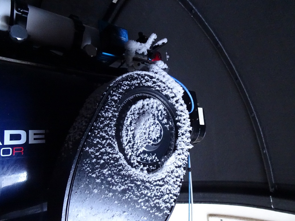
- Potential Snow entry through the gap between shutter and dome roof near zenith
(snow protection routine for automatically rotating roof to minimise risk
- Stutter during dome rotation (fixed
2021-01-15)
- Slabs to be laid around the rear side
of the observatory (still open)
Dome Geometry set up in Poth.Hub properties:
- Dome Slaving (checked, 2018-05-05)
- Dome Shutter Pointing (checked,
2018-05-05)
Issues:
- Pulsar Dome switching back and forth between USB
Serial Port COM9 and COM11 (2018-05-05) (Details)
- Incidence where Slaved Dome
operating around azimuth 70deg +/-, whilst scope operating around azimuth 190
deg +/- (2018-05-05)
- 'Unexpected' Dome Movements as the Dome
synchronises every few minutes with Telescope Pointing (2018-05-05)
(can Dome be set to move at 1.0x sidereal and be slaved at same time to
alleviate this problem ? )
- Shutter battery shows maximum charge of
51% (2018-05-03)
The following problems were identified and have been fixed:
- Cloud Sensor UTC times not converted to BST time (fixed,
2018-04-29)
- Sun information being accessed by Observatory Manager thread
every 30s interferes
with user's use of TheSky program
(part fixed, 2018-05-05)
- Program crash whilst performing plate solution
attempts (fixed, 2018-05-05)
- DarkSky.Net UTC times not converted to BST time (fixed,
2018-05-07)
The following problems were also identified but remain open, i.e. are unfixed:
- Unexpected alerts from Obs.Manager reporting that A/C power has been off for 20 minutes (open)
Following enhancements are identified
- Instruct dome to 1.0x sidereal (ie tracking), Instruct Dome to
0.0x sidereal (ie stopped) - Medium Priority
- Access Shutter Battery reading
and issue alerts as appropriate and close shutter or not open till battery
charge is acceptable - Medium Priority
Rotation Rate of Dome (sidereal) must be set to 0.00x sidereal when using POTH.Hub's Slave Dome function. If not TheSky6 doesn't recognize that a telescope slew has been completed (as it sees that Dome is still moving). As a consequence the control program doesn't respond with the next program step
Tasks Completed :
- Focusing (ok, 2018-05-05 & 2018-05-17)
- Main Camera Alignment
(ok, 2018-05-05, ~180 deg (N down) due to camera leads)
-
Telrad Alignment (done, 2018-05-05 , Arcturus)
- Synchronise on Object (done,
2018-05-05, Arcturus)
- Set Telescope Park Position (done, 2018-05-05,
Alt 0 deg, Az 180 deg)
- Set Scope to get Time/Date from Computer via POTH Hub (done,
2018-05-05)
- Provisional Polar
Alignment (done, 2018-05-10 / 2018-05-)
- Periodic Error Measurement (done,
2018-05-13))
- Set Scope to not use GPS (done, required as guidescope presence stops the LX200
from getting a GPS fix)
-
PEC curves uploaded (done, 2018-05-16)
- TPoint Mapping (first
run done, 2018-05-17))
- GuideScope focus and alignment (done,
2018-05-22)
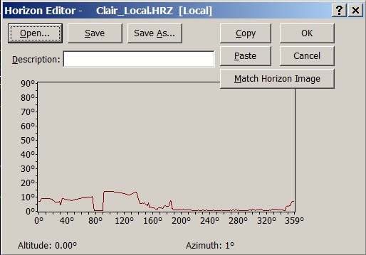
- Map Local Horizon (done, 2018-05-22)
- Clear View
Checks, including Zenith (done, 2018-05-22)
- Observing Run using
Computer Generated Schedule & Automated Execution (done, 2018-06-11)
- Stress Test (done, 2018-06-13)
Tasks To Do :
- Fine tune
Polar Alignment (to do)
- Collimination (to do)
Local Horizon Mapped :
|
Mapped Horizon (Horizon Altitude varies between 0 and 14 deg) |
 |
- Slewing Safety Check, looking at Telescope/Camera cable travel was
successfully conducted ahead of session on 2018-05-17 (pictures).
No telescope lead issues surfaced during mapping of 121 points during session
itself
- 12V Cigarette Lighter Connector became accidently disconnected
during session on 2018-05-17 causing dew heater to go offline.
(a
better solution is required)
- Addition of a cable protector/guide on
2018-05-23 may have been responsible for a series of Telescope Communication
Errors seen during the next two sessions by pressing too tightly on RS232 Cable
to the Scope (this was
later fixed by
relieving the pressure on cable)
Additional equipment required
- focuser controller for 80mm guidescope
- LED strip lights for
Cabinet/Bays
- Dehumidifier
- Completed : Extra Floor Strip for carrying cables across
floor from cabinet to scope
- Completed : Interior Door Mat
- Completed
: New 12" Dew Strip
to place inside Dew Shield (purchased but not yet fitted)
| Commissioning Session |
ID | Test / Task | Result | Highlights | |||
| 2018-05-05 | S610.1 | Start Up | Issues | Partly successful, but several issues. | |||
| (night-time) | Control Program | Issues | Critical problems encountered with Observatory Control Program | ||||
| Focus | Ok | Adequate for commissioning setup and tests | |||||
| Camera Orientation | Ok | (Orientation 180.0 deg+/-) | |||||
| Telrad Alignment | Ok | (Took a long time) | |||||
| Centre Align Star & Sync | Ok | (Arcturus) | |||||
| Set Park Position | Ok | (Az 180, Alt 0) | |||||
| System Stability | Issues | Issues with Dome Com Port jumping and Slaving/Telescope LST | |||||
| 2018-05-08 | S610.2 | Start up & Slaving | Ok | POTH.Hub connected & functioning ok | |||
| (night-time) | Centre Align Star & Sync | Ok | (Arcturus) | ||||
| Polar Alignment | Fail | Not achieved due to developing cloud. | |||||
| Parking / Close Down | Ok | Earlier alert message problem fixed | |||||
| System Stability | Ok | Session was short | |||||
| 2018-05-10 | S610.3 | Periodic Error |
Ok | Successful check. Normal PE trace (35" peak-to-peak, PEC off) - Graphs | |||
| (night-time) | RA Motor Unit | Ok | Confirmation that installation of new RA motor unit giving required benefits | ||||
| Polar Alignment | Ok | Provisional Alignment Completed (~ 2' Azim / 0.2' Alt) - Graphs | |||||
| System Stability | Issue | Issue with Telescope/POTH loosing the correct LST | |||||
| 2018-05-11 | S610.4 | Trun off GPS | Ok | GPS Turned off (allows 80mm guidescope to be left on between sessions with GPS Fix issues at next start-up | |||
| (daytime) | Auto Time Update | Ok | Time updated to Computer's Time upon Scope connection | ||||
| 2018-05-13 | S610.5 | Start Up | Ok | ||||
| (night-time) | Periodic Error | OK | RA tracking measured across 2 x 24min worm cycles | ||||
| PEC Upload | Fail | PEC curve not correctly sychronised to Worm Segment Counter (shifted curve prepared ready for upload at next session. - Graphs) |
|||||
| Remote Control | Ok | Observatory operated under remote control for part of session | |||||
| Polar Alignment | Ok | Alignment further refined using PemPro Wizard -
Graphs (alignment estimated to be within 1.5 arc min of Celestrial Pole) |
|||||
| System Stability | OK | System not pushed excessively | |||||
| 2018-05-16 | S610 | PEC Upload | Ok | PEC Curves successfully uploaded to mount. | |||
| (night-time) | Periodic Error | Ok | Residual PE Error used to further refine PEC curves (2 iterations), PE < +/- 3 arc mins - Graphs | ||||
| First Images | Ok | First set of images taken, including unguided images with up to 180s exposure.- Images (S610) | |||||
| System Stability | Ok | System stable throughout session. | |||||
| Remote Control | Ok | Observatory operated under remote control for majority of session. (Observatory opened and closed from inside house.) |
|||||
| Flat Frames | Ok | Sets of Flat Frames where acquired with C filter | |||||
| 2018-05-17 | S611 | Slewing Safety | Ok | Slewing Safety Check successfully conducted (Pictures) | |||
| (day-time) | |||||||
| 2018-05-17 | S611 | Focus | Ok | Semi-Automated focusing run successfully conducted (Details). | |||
| (night-time) | TPoint Mapping | Ok | 121 points successfully mapped (25% Automap rejection with Error Code 653) | ||||
| TPoint Model | Ok | TPoint Model built (Details), polar alignment elevation ME sensitive to other terms used in the mode. | |||||
| Polar Alignment Review | Ok (part) | Polar Alignment Information from TPoint run (Polar Alignment review) | |||||
| System Stability | OK | System stable throughout session. | |||||
| 2018-05-22 | S611.2 | Align Guidescope | Ok | Guidescope aligned with LX200 Main Scope | |||
| (day-time) | Map Local Horizon | Ok | Local Horizon mapped and uploaded to TheSky6 (Details) | ||||
| Clear View Checks | Ok | Clear View Checks completed, including checks around Zenith (Some issues near to Zenith) |
|||||
| System Stability | Issue | System generally stable but a couple of glitches noticed that could be problematic for unattended operation | |||||
| 2018-06-06 | S612 | TPoint Model | Ok | Synced into TPoint Model | |||
| (night-time) | Images | Ok | Partly achieved with images of Jupiter & its moons (Pictures) | ||||
| Observing Plan | Fail | Not achieved due to POTH/Scope/CCDSoft Instability (Observing plan) | |||||
| System Stability | Fail | System very unstable with frequent disconnections to tthe Scope. Also problems with Dome COM port (9 & 11), freezing of CCDSoft, and upset to scope's LST (Operational issues) | |||||
| 2018-06-08 (day-time) |
S612.2 | Observing Plan | Ok | Observing Plan successfully executed using live observatory hardware, but without plate solution/centering (no stars in daytime) (Observing plan) | |||
| System Stability | Issue | System initially unstable with disconnection to scope, freezing of CCDSoft5 (Operational issues) | |||||
| 2018-06-11 (night-time) |
S613 | Observing Plan | Part OK | 5 Targets successfully acquired with automated execution of computer generated observing plan / schedule. Issues with accuracy and time take for high precision target centering, time overruns and missed start times for following target. (Observing plan) | |||
| Images | Ok | Some images acquired (Pictures) | |||||
| System Stability | Fail | System very unstable in first half of session with frequent incidences of telescope communication error '213' / automatic termination of telescope link. Also problems with freezing of CCDSoft5 and Dome COM port switching (9 & 11) as side-effect of '213' error. (Operational issues) | |||||
| AllSky | Fail | AllSky Laptop failed with a terminal hard disk failure (Failure & Replacement) | |||||
| 2018-06-13 (day-time) |
S613.2 | Stress Test | Ok | 2 hour long Observing Plan (74 target) successfully executed using live observatory hardware & software, but without plate solution/centering (no stars in daytime) (System Stress test) | |||
| System Stability | Ok | System stable, without any repetition of telescope communication error '213' | |||||
Back to Top
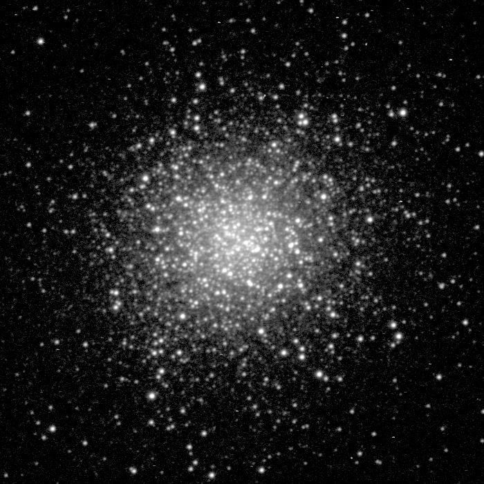
| First Light Image from the new observatory,
2018-05-17 M13, Globular Cluster (Hercules) |
|
| CCD Image (100% size, cropped, logscale), 7 x 10s exposure (average combine), 2x2 binning, C Filter 2018-05-17 00:25 h UT (#610045-51) 12" LX200R (at f/10.4) + ST-10XME |
Back to Top
Dome Clamps |
||
| Dome Clamps - Fitting Issue (2018-04-21) A problem was noted with the batch of dome clamps I was initially supplied with. The slots for taking retaining bolts didn't align with the wall flanges) (replacement clamps are due to be sent out in due course. They are understood to be sent out soon - Sep 2018) |
||
|
|
||
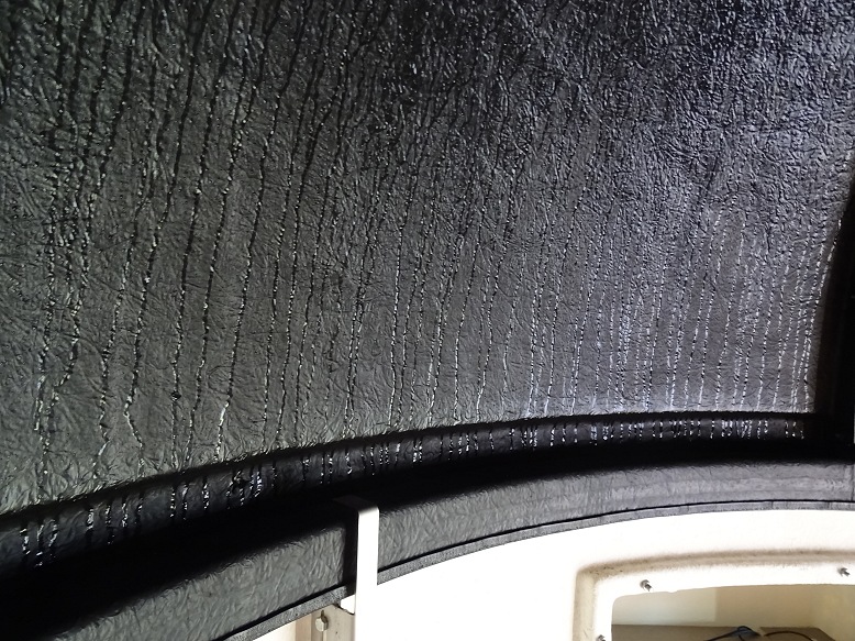
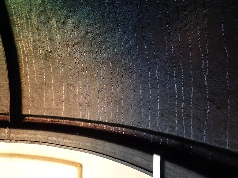
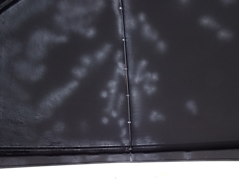
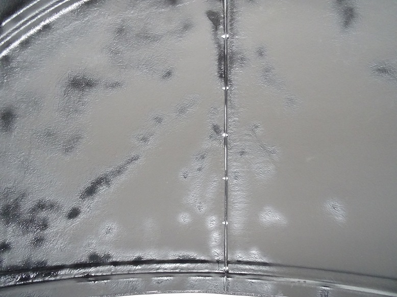
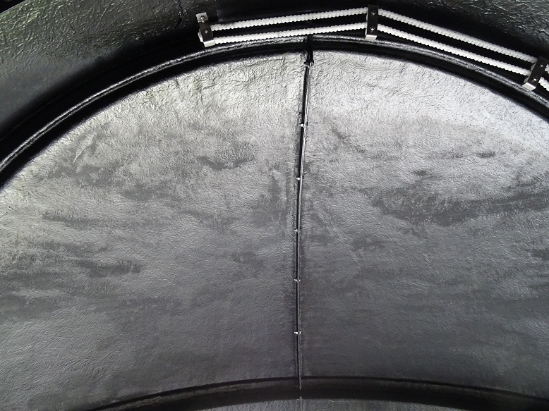
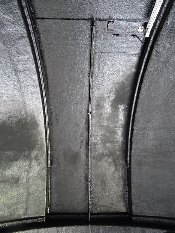
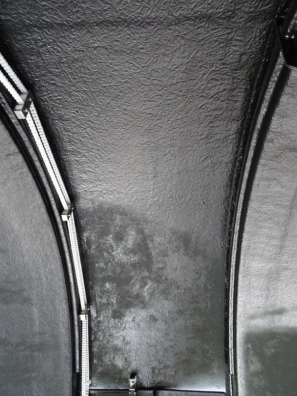
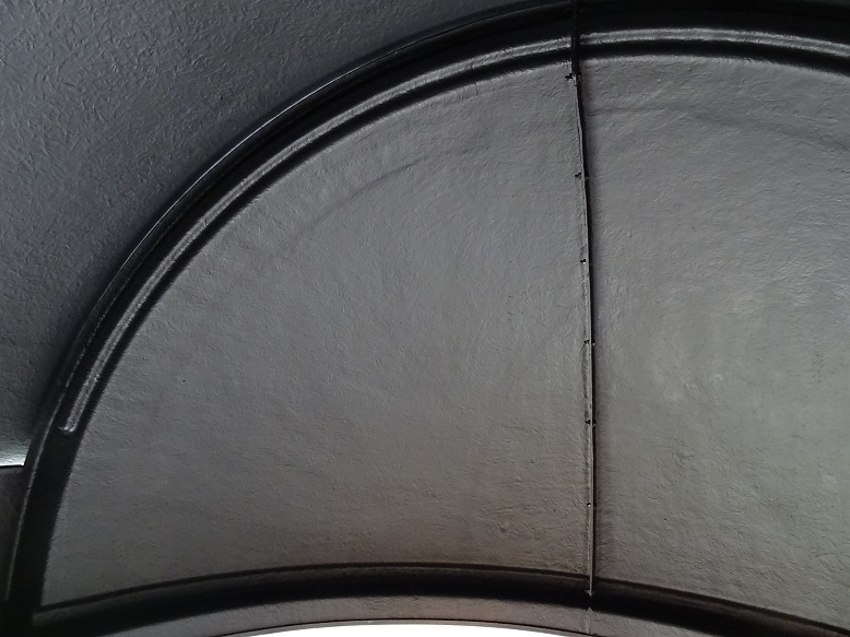
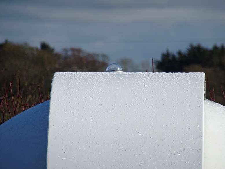
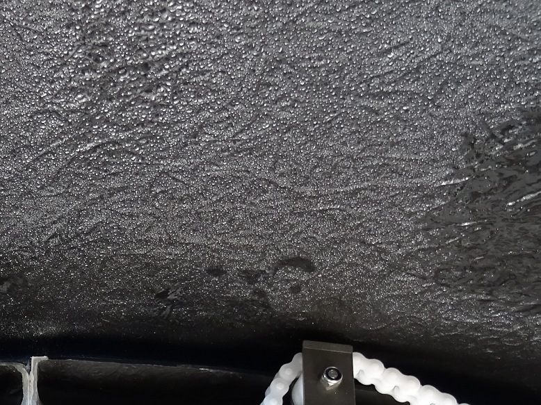
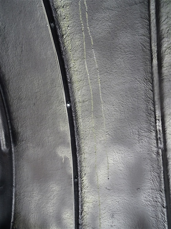
| Condensation on Roof Interior (2018-04-21) Condensation was particularly bad during the first two weeks, but settled down over the summer months. It will be monitored as the winter season is approached to see if a Dehumidifier is required. |
||
| Condensation on roof interior (high up on ceiling) |
Condensation on roof interior (detail) | |
 |
 |
|
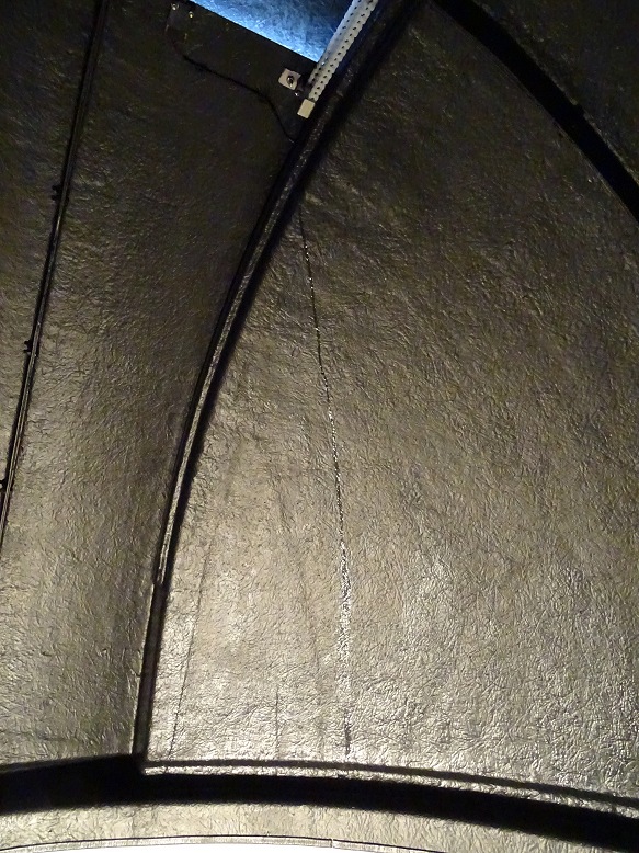
| Water drip lines related to condensation on roof interior (taken before Dome Roof Paint Remediation) |
Water drip line on shutter interior | |
 |
 |
|
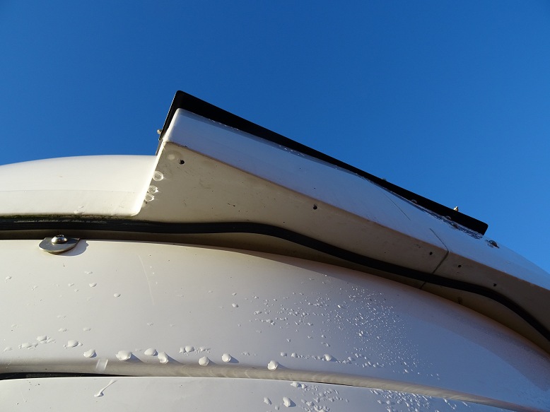
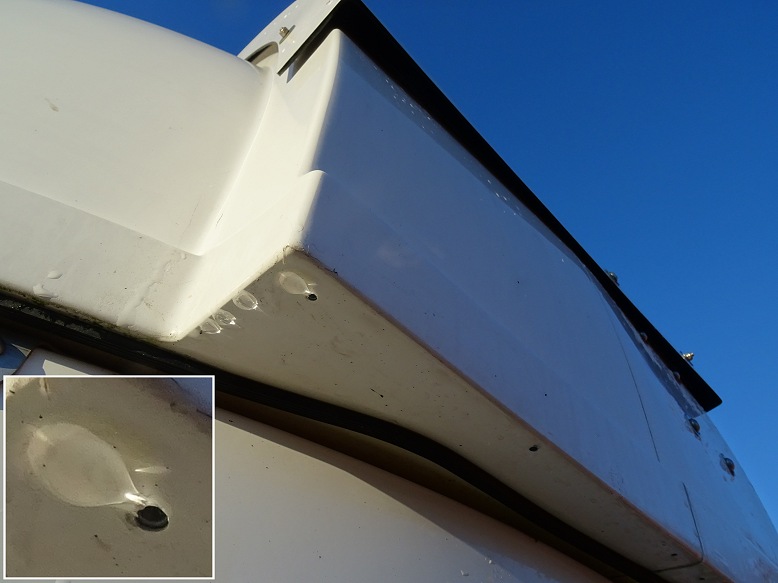
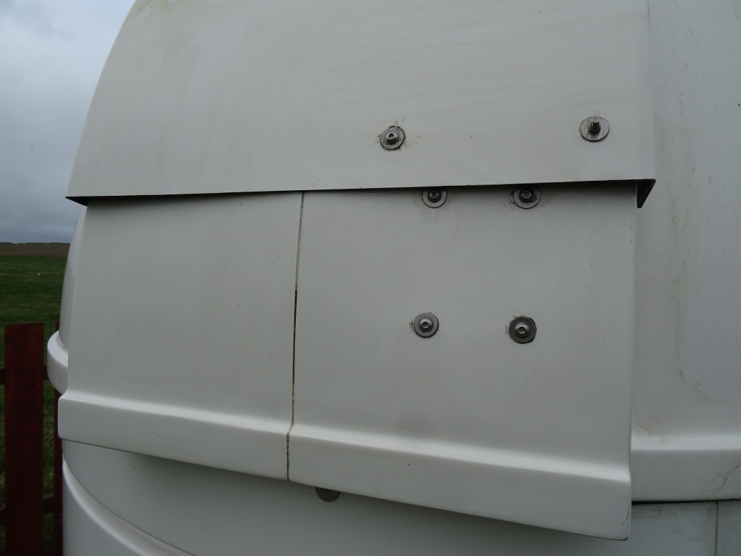
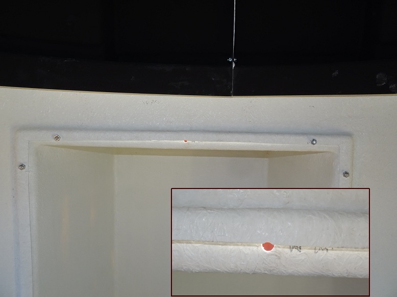
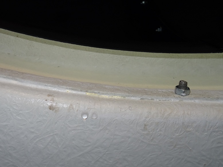
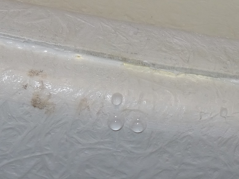
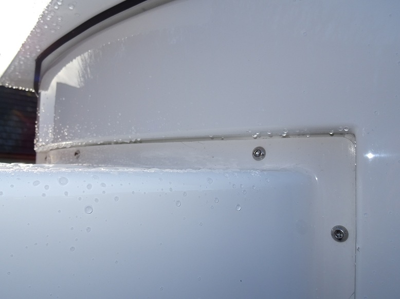
| Water drops from Small Leak along top of Bay |
Water drops from small leak along top edge of one of the bays |
|
| Small Water Leaks Above Each Bay (2018-04-25) | ||
| Top of Bay | Photo showing earlier problem fitting Observatory Bay | |
|
|
|
|
| Water drops from Small Leak along top of Bay |
Water drops from small leak along top edge of one of the bays |
|
 |
 |
|
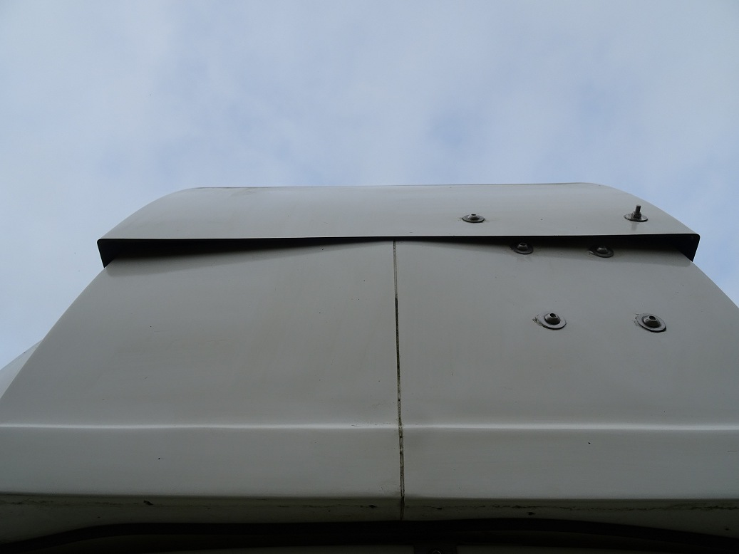
| Outside view showing leak path along top edge of bay (gap was later sealed with silicone) |
Outside view showing leak path along top edge of bay (alternate view) |
|
|
|
 |
|
| Cabinet Remediation (2018-05-01) | ||
| Water drip lines related to condensation on roof interior (drip lines like these fall down on to original cabinet desktops before being reduced in depth, drips will now fall onto floor from where water can safely evaporate (taken before Dome Roof Paint Remediation) |
Reducing Desktop /Shelf Depth (original surfaces were made with depth of up to 55cm, but water drops from heavy condensation one frosty night fell on to the surfaces damaging them in the process, The work surfaces were cut back to a maximum depth of 48cm so that they lay entirely within the bay) |
|
|
|
 |
|
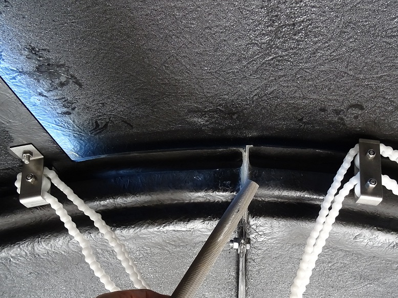
| Water Leak (2018-05-02) | ||
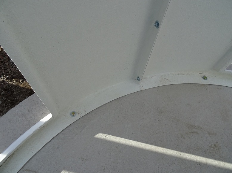
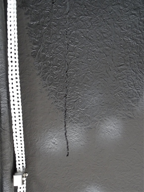
| Water Streak on roof interior (indicating a leak from somewhere in the upper roof, investigation shows this was due to rain entering from uppermost pulley fixing) |
Wet patch near uppermost pulley fixing (indicating a water leak from uppermost pulley fixing |
|
 |
 |
|
| Water Drip from bolt holding
uppermost pulley (investigation showed that one nut holding the fixing was loose, this was loosened whilst adjusting the pulley and evidently hadn't been retightened) |
||
 |
||
| Telescope Communication Errors (2018-06-06 to 2018-06-13) | ||
|
Cable Protector/Guide added on 2018-05-23 Protector addition may have given rise to Intermittent Telescope Communication Errors by pressing too tightly in RS232 Cable to Scope |
Cable Protector/Guide Recently added Cable Protector loosened to relieve pressure on RS-232 Cable Cable Connections fully checked |
|
|
|
 |
|
Back to Top
Ramp-up phase is the intended to gradually move the observatory into full
operation, by
- ironing out any remaining bugs and issues in the system
prior to the forthcoming winter season,
- adding and testing a key software
enhancement to enable fully-automated operation.
- increasing the time
devoted to taking proper astronomical images and to scientific programs.
Aims for the automated operation testing phase:
- Test routines in Observatory Control Software (CCDApp2) that are designed
to provided Fully-Automated Operation capability
- Identify and rectify issues
relating automated operation of the
observatory
- Ensure that robust safeguards are in place to ensure that
automated operation is safe
particularly with regard to shutter
opening/closing.
- Continue to test and prove system stability, and iron out
any remaining issues with the observatory.
| Session | Test / Task | Result | Highlights | ||
| 2018-07-18 (night-time) |
Fully Automated Test | Issues | Observatory System placed in Fully Automated Mode, which generally worked ok except that target slewing/imaging commenced with the Dome Shutter still shut (not opened due to adverse weather (cloud), which is in itself a positive result) (fully automated test) | ||
| System Stability | Ok | System stable, without any repetition of telescope communication
error '213' (Unable to 'unpark scope' however after parking at end of session) |
|||
| AllSky | Ok | AllSky & Weather Montoring Services back in action following incorporation of a replacement Laptop that was brought into service on ~2018-06-25+ | |||
| 2018-07-22 S614 |
Fully Automated Test | Issues | Observatory System placed in Fully Automated Mode and ran for second half of the night. (fully automated test) | ||
| System Stability | Ok | System stable | |||
| AllSky | Ok | Annototion of AllSky Visible Stars back in action following update to SExtractor settings. | |||
| 2018-07-24 S615 |
Fully Automated Test | Issues | Observatory System placed in Fully Automated Mode and ran for second half of the night. (fully automated test) | ||
| Observing Plan | Issues | Low imaging efficiency due to target observations overunning their allotted time slot causing the following target observation to be missed leading to wasted time whilst execution waits until the scheduled start time of the next planned observation. Mosaic Frame Imaging Mosaic Failed Fix to Mosaic Inaging worked. | |||
| System Stability | Ok | System stable. | |||
| AllSky | Fail | Outage of Cloud Detector (fixed by manually disconnecting and then reconnecting USB and Power cables) | |||
| 2018-07-25 S616 |
Fully Automated Test | Ok | Observatory System run in Fully Automated Mode for entire night. Newly added code to skip final image(s) to ensure target observation finishes within allotted time slot (and ensuring that the next target observation isn't missed) worked perfectly (fully automated test) |
||
| Observing Plan | Ok | Newly added code to skip final image(s) to ensure target observation finishes within allotted time slot (and ensuring that the next target observation isn't missed) worked perfectly. Fix to Mosaic Frame Imaging worked. | |||
| System Stability | Ok | System stable. | |||
| Monitoring | Fail | Indoor Desktop Computer out of action with terminal hard disk
failure (C Drive) (Fall-back is to use UltraVNC from IPad) |
|||
Back to Top
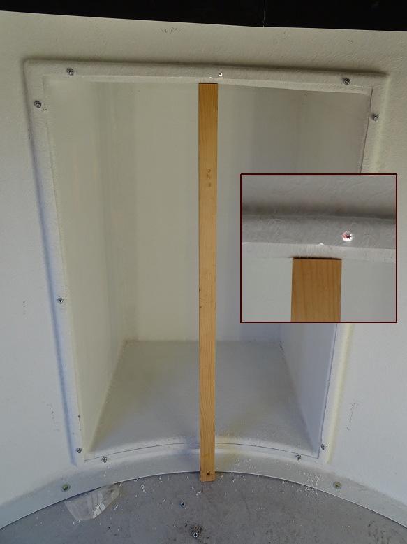
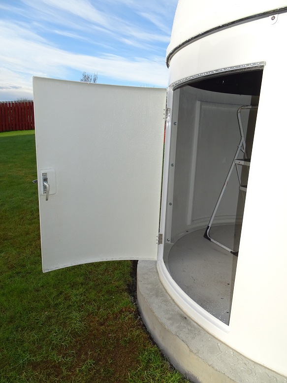
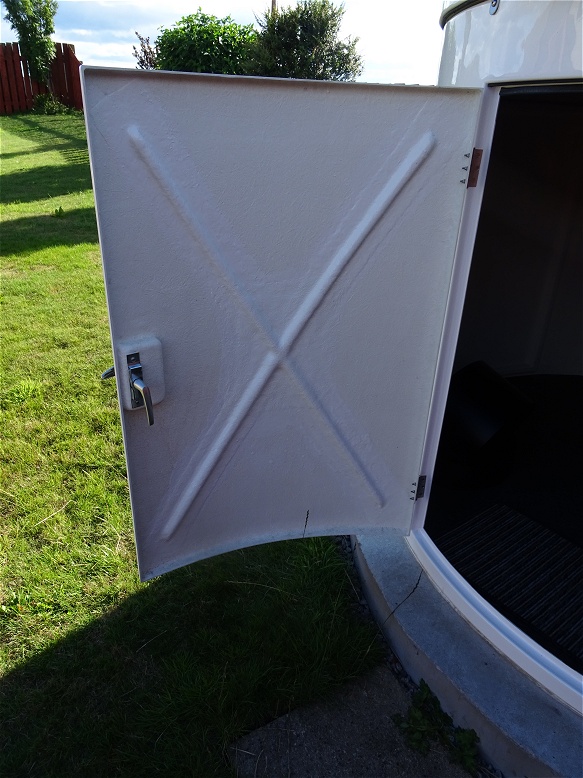
It was quickly noted after assembly and first use that the door supplied with Pulsar 2.2m dome observatory is very flimsy and easy bends /wobbles under its own weight when its open. I finally got around to having the observatory door stiffened up using shaped wood & fiberglass cross-pieces in August 2018. The remediation was performed at a local fiberglass workshop for £60.
|
Observatory Door - as supplied Flimsy & bends too easily under its own weight |
Observatory Door - stiffened Door stiffened up by the addition of shaped wood & fibreglass cross pieces |
|
|
|
 |
|
Back to Top
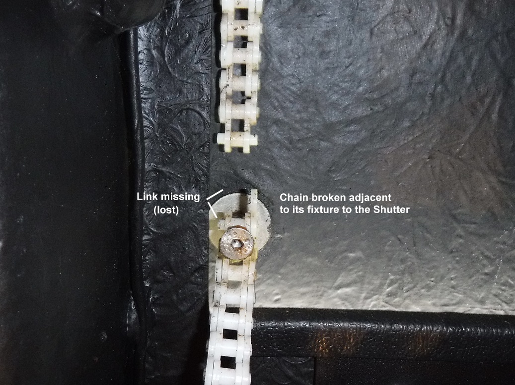
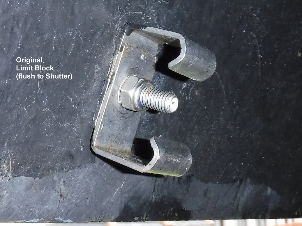
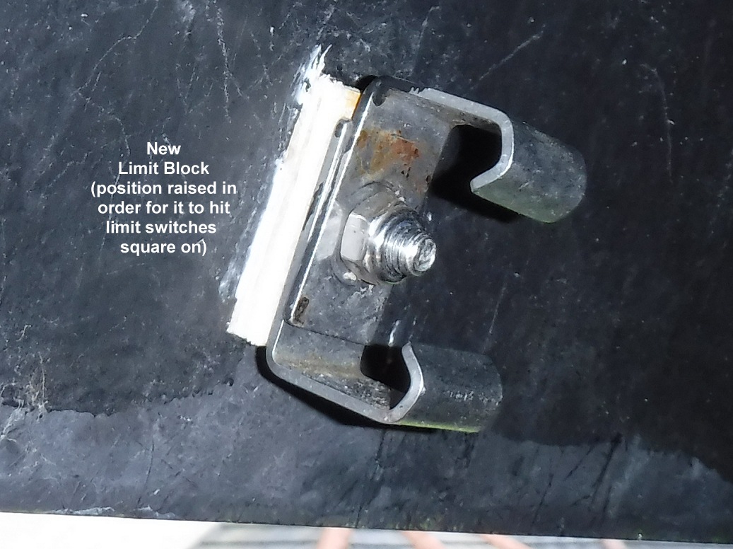
After using the Shutter Drive for a while it became obvious that its position wasn't sufficiently correct and that there was a misalignment between the drive sprocket and the line of the plastic chain that pulls the shutter open and closed (a risk of a self-installing a dome for the first time). Slack chain would develop close to the drive unit when the shutter began to open until the shutter reached the first xxxx. leaving one with some lack of confidence in the system. No amount of tension adjustment was able to stop this slack from developing. It was also apparent that there would probably be long term wear on the side of the plastic chain that pushed against the metal drive sprocket the most, with eventual risk of failure. There might also be some extra wear on the connection of the sprocket to the drive axis or on the drive axis itself. Relocation the shutter drive unit so that the drive sprocket would align perfecting with the chain was put down as a 'task to do' - a job to do some time before the winter season.
The need for this remedial fix came to head following an incident during the observing session on 2018-08-21 when the chain jumped off the drive sprocket when the motor tried to open the shutter from a closed position. With the shutter not moving and unable to close the relay at top of dome, the motor continued running for 45 minutes in a vain attempt to open the shutter before the observatory was visited and drive turned off. The problem wasn't picked up via remote monitoring as the observatory control program was putting out continuous messages that it was closing the shutter due to cloud, wind and threat of rain (from local rain radar). The incident highlighted several things, but among them was the need to correct the current installation deficiencies and relocate the shutter drive in order to prevent or strongly reduce the risk of another chain problem in the future.
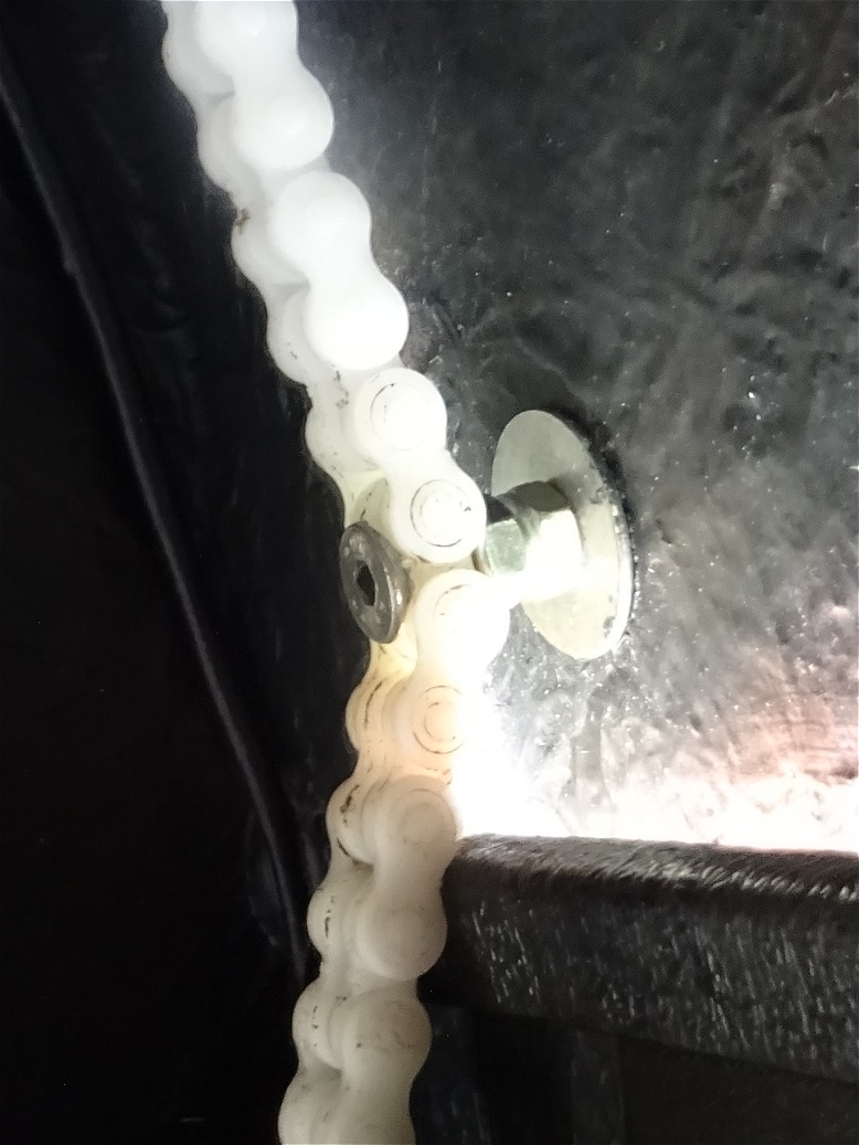
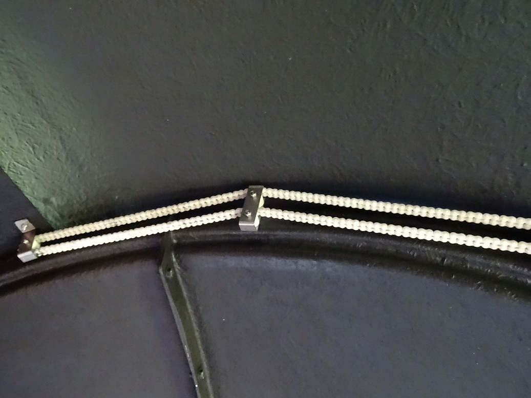
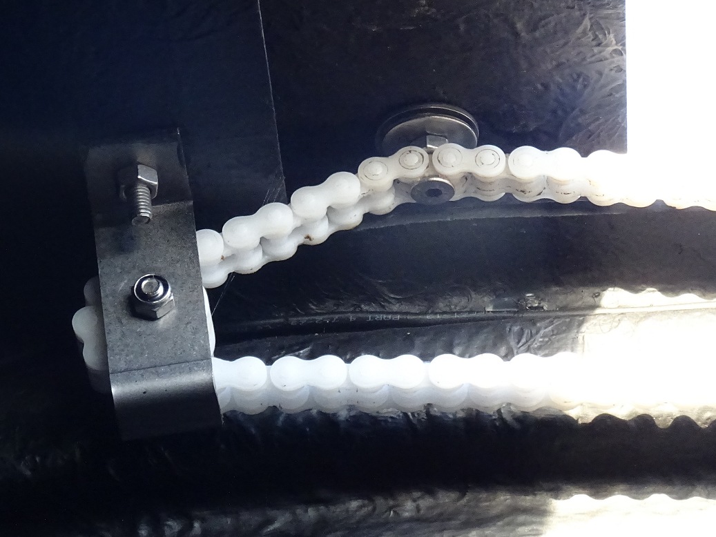
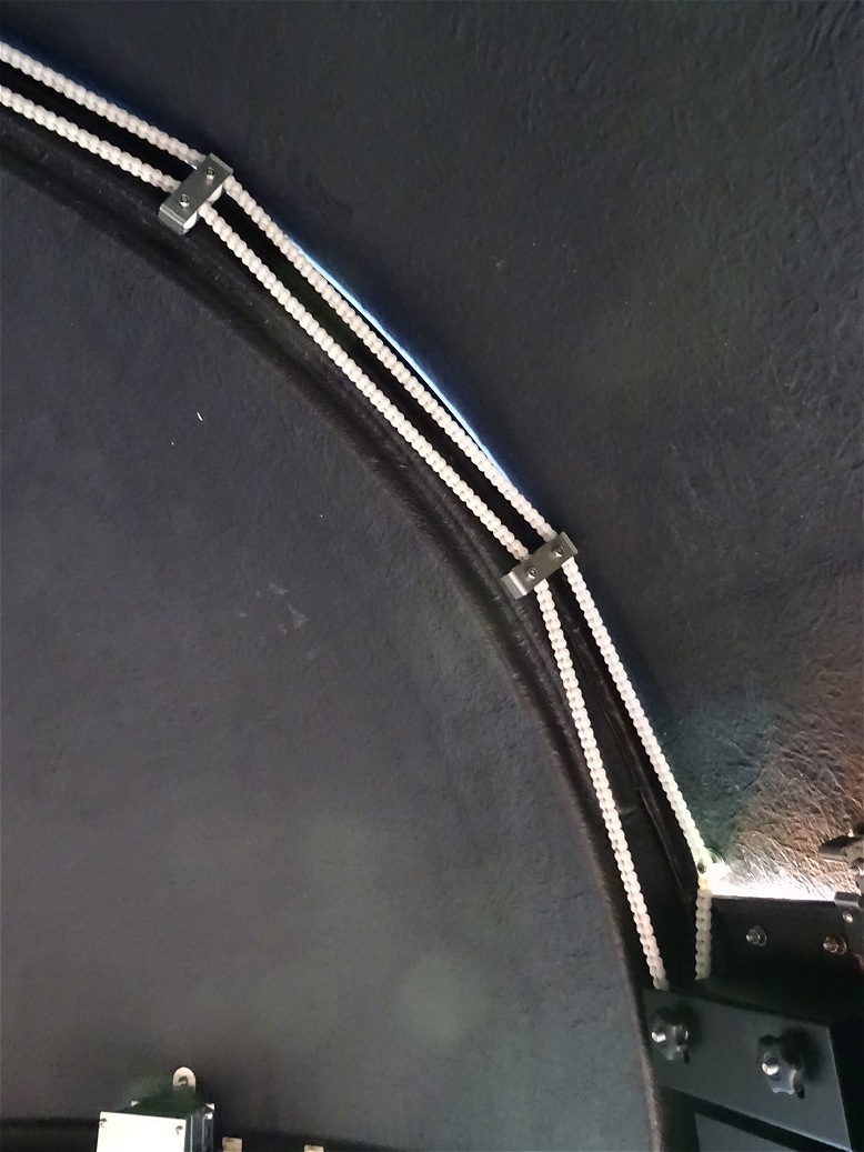
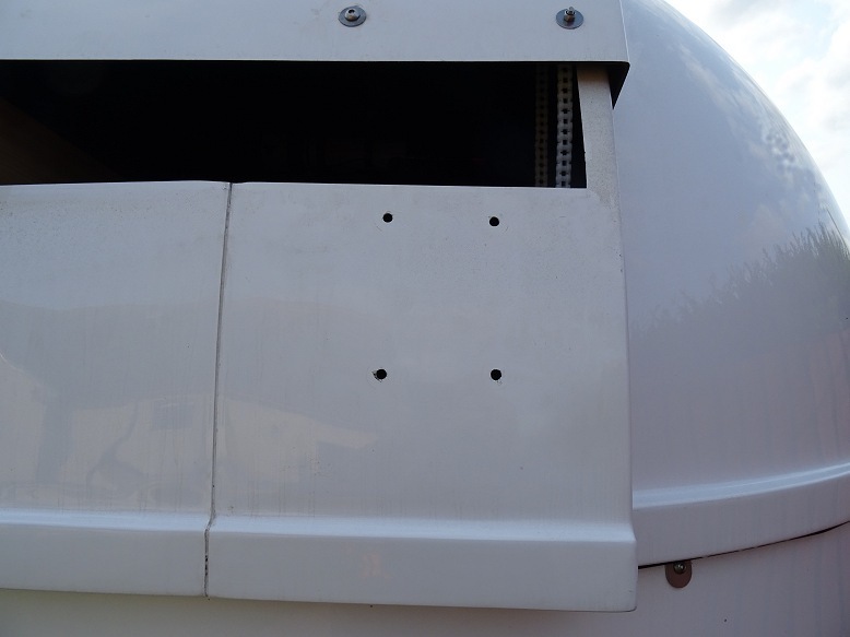
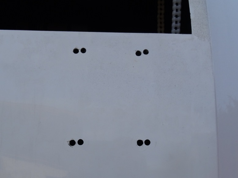
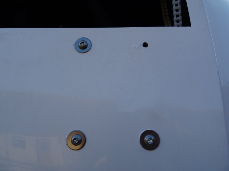
Pictures below taken whilst re-locating the shutter drive unit the following day (2018-08-22). The drive unit was shifted across by 10mm. It was noticed that the drive sprocket was somewhat loose and the opportunity was taken to correctly position the position it on the axle and tighten up the retaining grub screw with a suitable Allen key. It was necessary to move the bracket that comes in contact the relay attached to the shutter drive unit to ensure reliable closure of the relay. This was by a small amount only as the bracket still had to reliably hit the relay at the top of shutter travel. The chain is now perfectly aligned with the drive sprocket and works more smoothly, and my confidence in the system is again restored.
It is noted that a slack in the chain on the 'downstream' of the drive
sprocket is still created in the process of opening the shutter. Hopefully
with the perfectly aligned chain/drive sprocket the chain can't manage to crawl
its way off the sprocket.
(The slackness created when opening the dome
appears to highlight a weakness in shutter system due to the inherent
changes in the total direct path distance around the various pulley wheels and
sprocket as the shutter open/closes. Ideally the system would incorporate a
'tension wheel' that would maintain a constant tension in the chain whatever the
position of the shutter.)
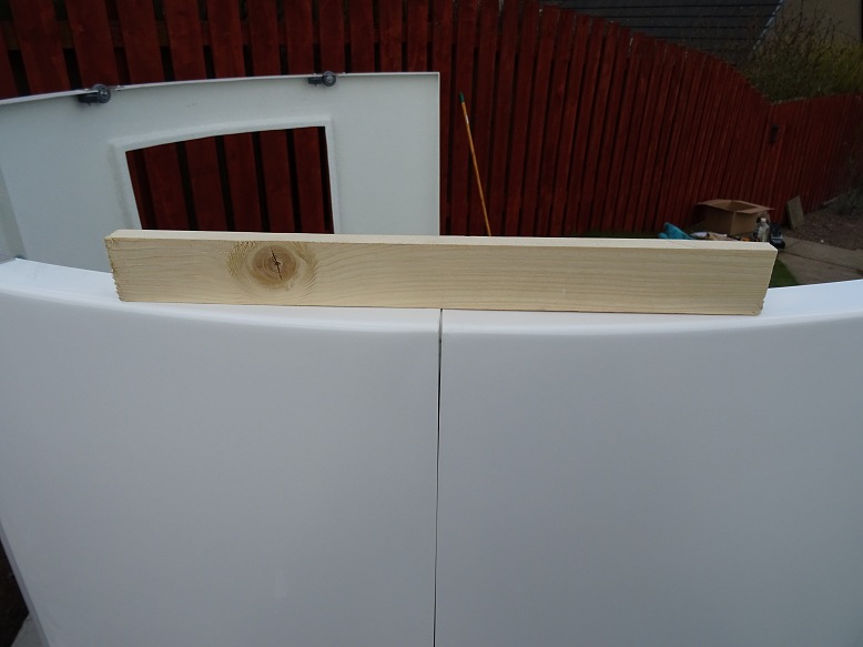
|
Shutter Drive Unit removed (a piece of timber (out of view) is being used to hold the shutter open) |
New Holes drilled (10mm to right of original holes) |
|
 |
 |
|
|
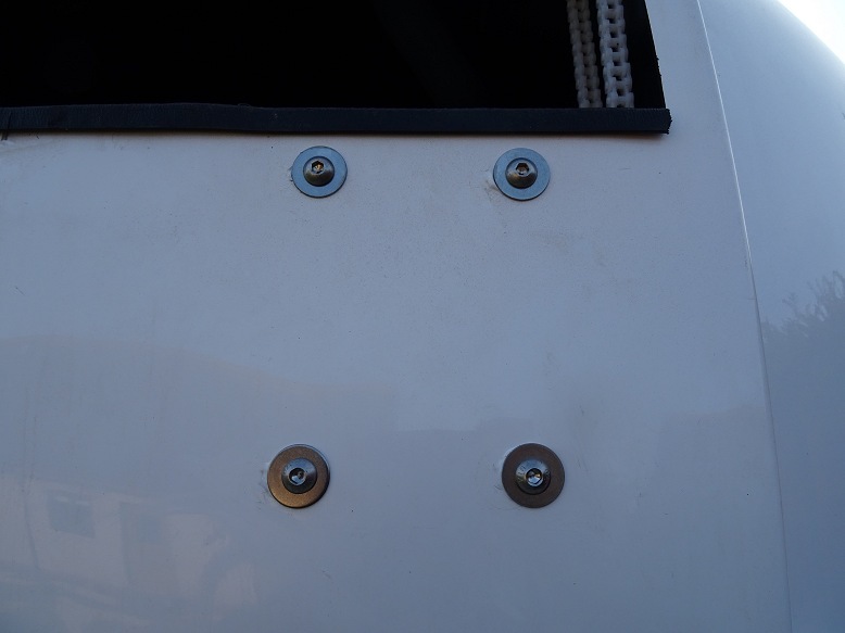
Re-Installing Shutter Drive Unit (Old holes covered on the inside with tape and then filled from outside with white sealant. They end up largely covered by the washers on the new holes) |
Shutter Drive Unit installed in the new position |
|
 |
 |
|
|
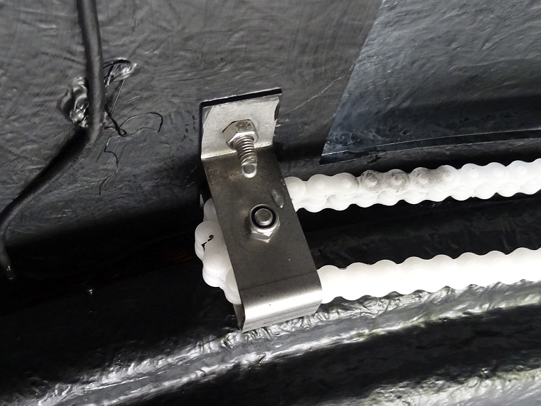
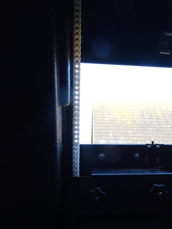
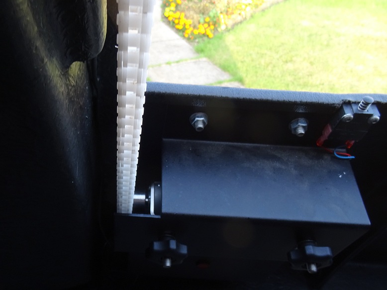
Chain reattached to Drive Unit (Chain run is now perfectly straight) |
Chain aligned with drive sprocket | |
 |
 |
|
|
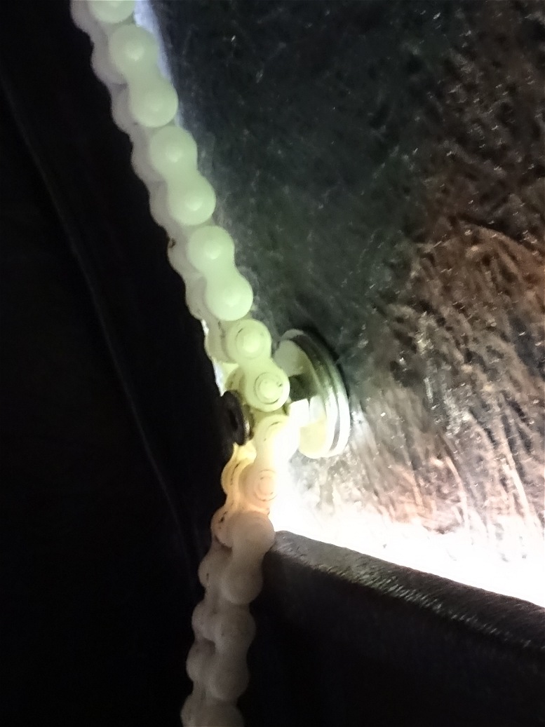
View of Chain with shutter closed (chain is nicely tight) |
View of Chain with shutter partly opened (chain goes slack on downstream side of the drive sprocket when the total direct path length reduces - this highlights an ongoing weakness in shutter system, but eventually fixed in Jan 2021 |
|
 |
 |
|
Back to Top
The Dome Clamps that were originally supplied with the Pulsar Dome Order in April 2018 didn't fit, as the slots for taking the retaining bolts didn't align with the wall flanges. Apparently the clamps sent out by Pulsar Observatories at this time had used the clamp design associated with the wall-less Dome and not for the walled Dome, and a new batch needed to be manufactured. The new clamps were finally delieved in late September 2018 and where successfully fitted in the observatory on 2018-10-03.
There are four dome clamps that are designed to provide a permanent in-place security to prevent the dome roof from lifting in strong wind or from being removed. Whilst the observatory gave no indication that the roof would be likely to lift in winds, the observatory site is close to the sea and pretty exposed to the winds. Having previously had my roll-off roof blown off former shed observatories I'm very pleased to have new clamps installed before the inevitable autumnal/winter storms arrive.
New Dome Clamps (finally delivered and fitted) |
||
 |
 |
|
Back to Top
Back to Top
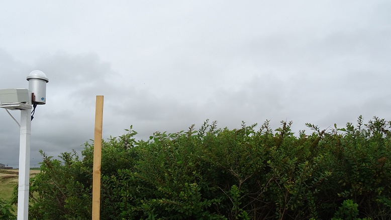
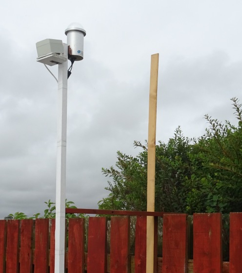
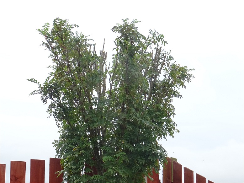
Opportunity taken today to some maintainance around the observatory.
|
Observatory Exterior getting a good cleaning with warm soapy water & sponge |
Northern hedge line trimmed so that it doesn't obscure
northern sky from aurora monitoring AllSky Camera |
|
 |
 |
|
|
Temporary 'shield' to block an annoying bright worksite security light |
Garden Tree trimmed so that it doesn't obscure southern sky from low Declination targets |
|
 |
 |
|
Back to Top
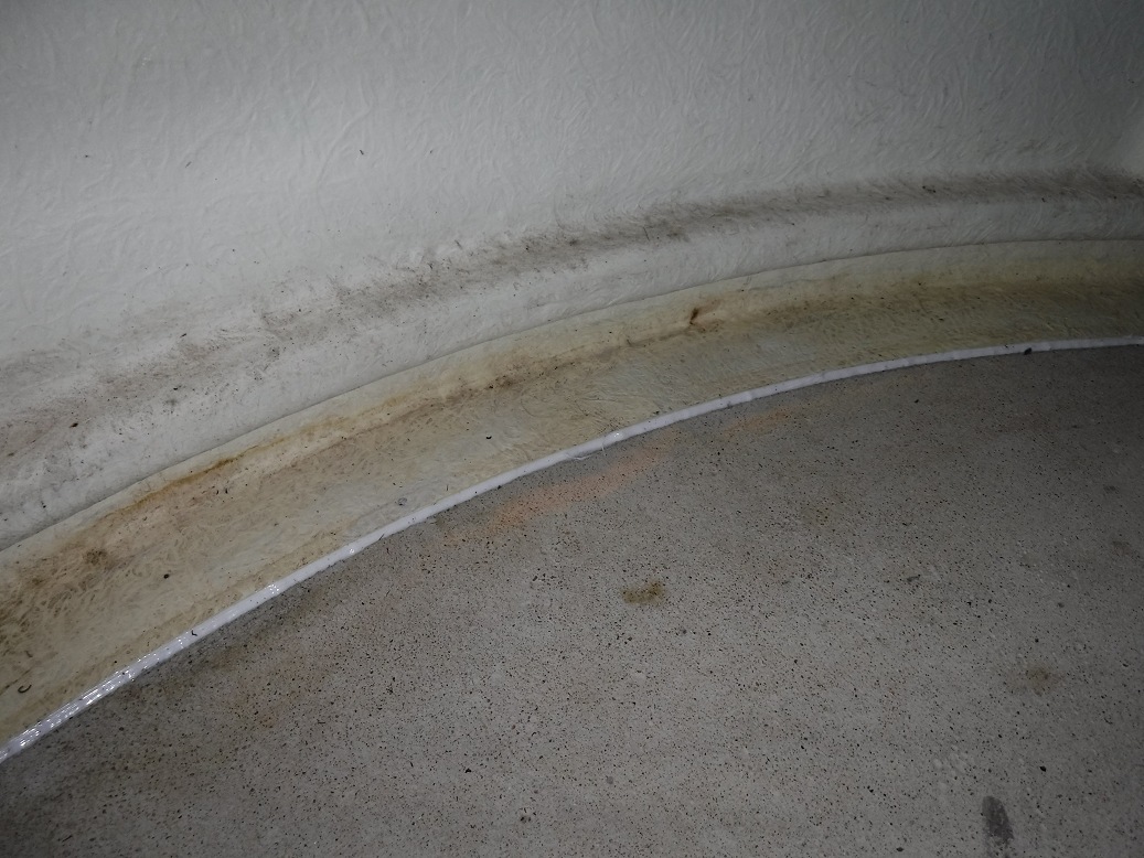
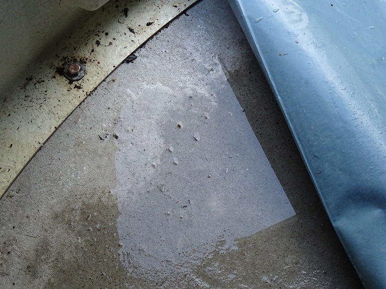
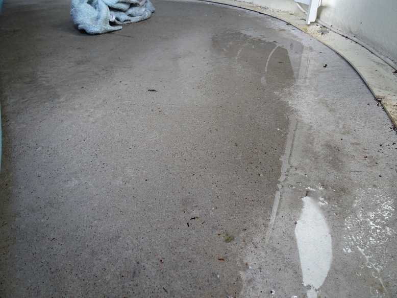
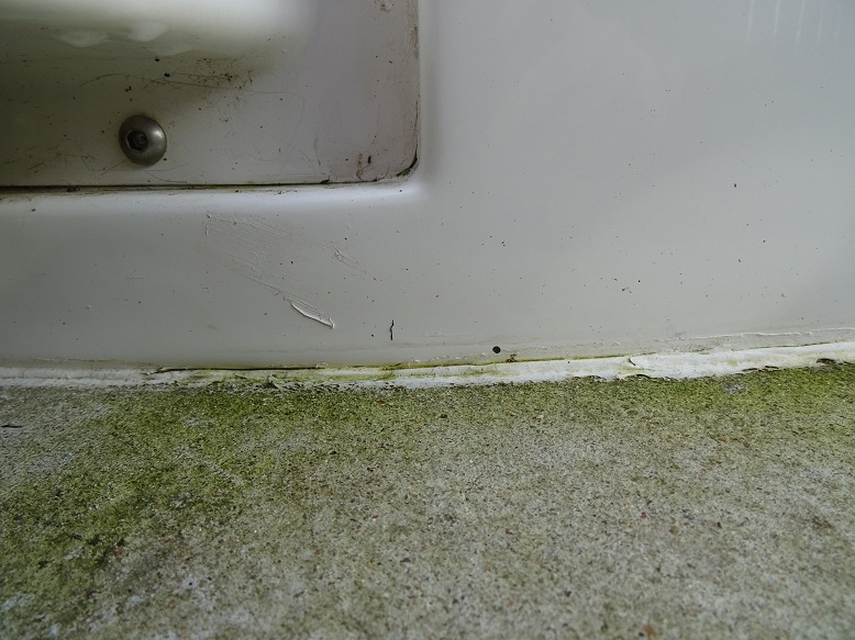
There was a very heavy rain storm on the morning of 2019-10-18. It was the sort of deluge that overflows the gutters and lifts the drain covers (not literally, but the water was forcing its way out of the drain cover sides and 'boiling' 5cm into the air !). During a visit to the observatory the following day, it was noticed that there was a distinct feeling and sound of water squelching under the rubber floor tiles, and there was water coming up through the gaps between the tiles when pressure was applied.
Pulling back the floor tiles and investigating revealed a huge puddle on water on the floor of the observatory, both on top of and under the plastic membrane.
Pictures of the Puddle on Observatory Floor following deluge on 2019-10-18 |
||
 |
 |
|
The rubber floor tiles were lifted and removed and towels used to soak up the large puddle of water.
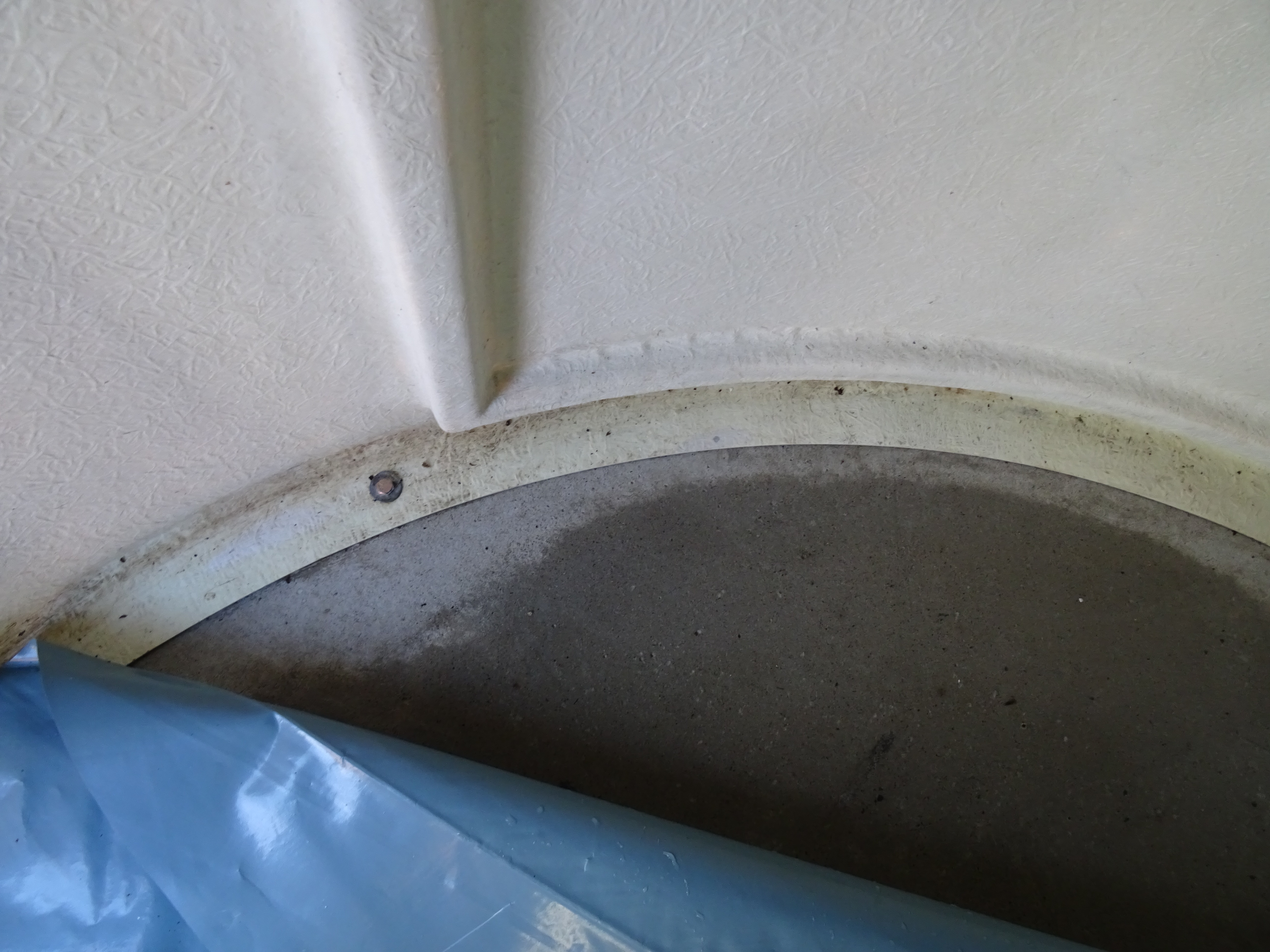
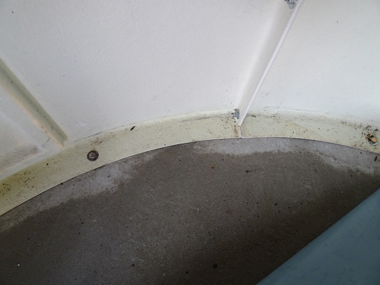
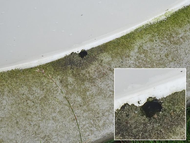
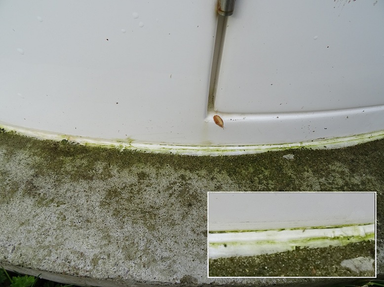
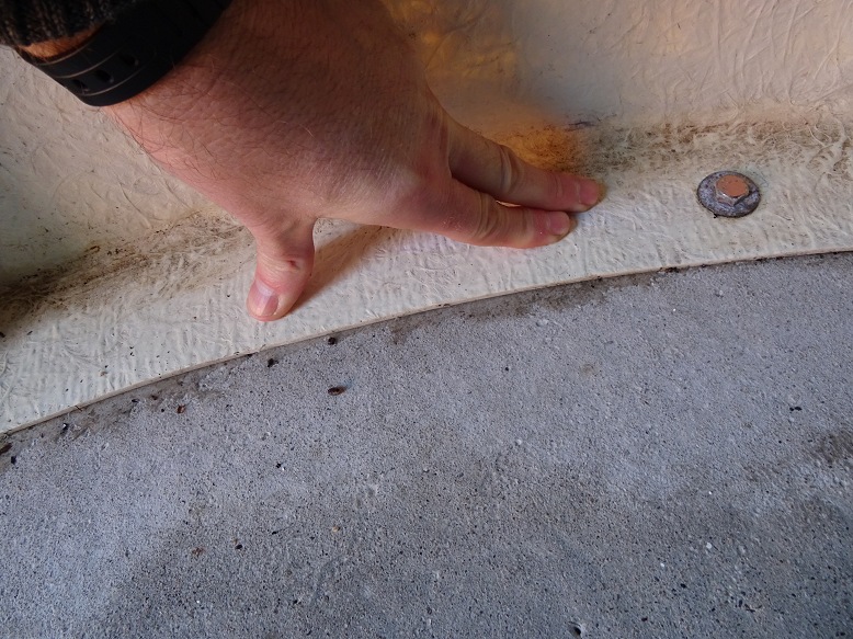
After the puddle was cleared an investigation began into how the water got into the observatory:
Investigating how the water got into the observatory (2019-10-19 & 2019-10-20) |
||
 |
 |
|
 |
 |
|
 |
 |
|
First Repair Attempt
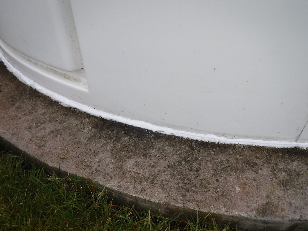
An emergency repair was made a few
days later in which the sealent was replaced along all the sections of
observatory based with obvious weakness. However this remedial repair was
unsuccessful and water continued to seep under the walls from multiple points.
It was concluded that the repair had failed and during a second remedial repair on 2019-11-18, it was evident that the sealent in the first repair attempt has failed to bond to the concrete, during to dampness in the concrete and the seep of built up water still lingering under the wall.
Sealent along observatory base was eventually fixed by a second repair fix on 2019-11-18
Back to Top
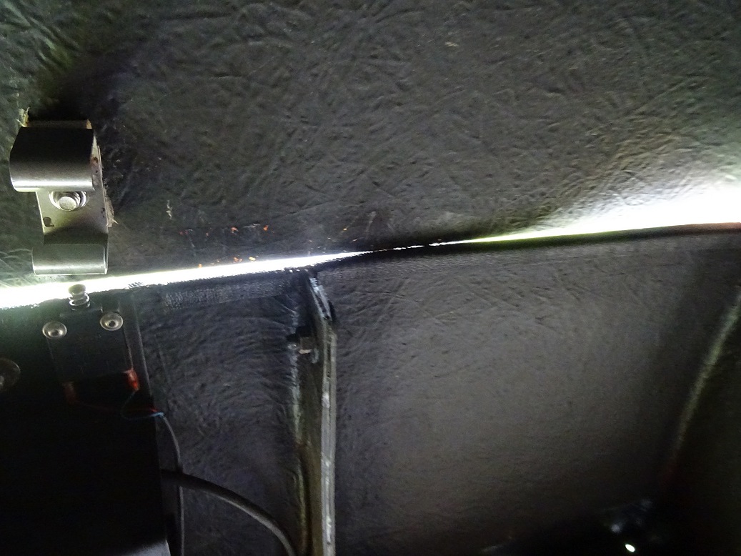
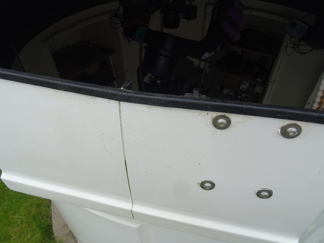
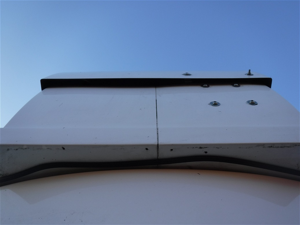
At some point during the session on night 2019-10-24 the Reinforced rubber edge trim that normally sits around the dome flange edge became detached and then proceeded to peel itself off as the dome rotated. This was only noticed when the observatory was visited the next morning. No damage seems to have been done apart from some abrasion to the rubber strip as it was forced through one of the metal roof retaining clamps. It is assumed that the incident happened at 03:14 when one particular slew (to GCVS GK Per) took an anomalously long time taking 6.9 mins to complete a 137deg azimuthal slew (i.e. a speed of only 20 deg/min).
The rubber strip was re-fitted to the flange taking care to press the reinforcement tighter in order to make it fit tighter to the dome flange especially at the the two ends. I think this is the second time that this has happened.
Pictures showing the Reinforced Rubber Trim that had detached
from
|
||
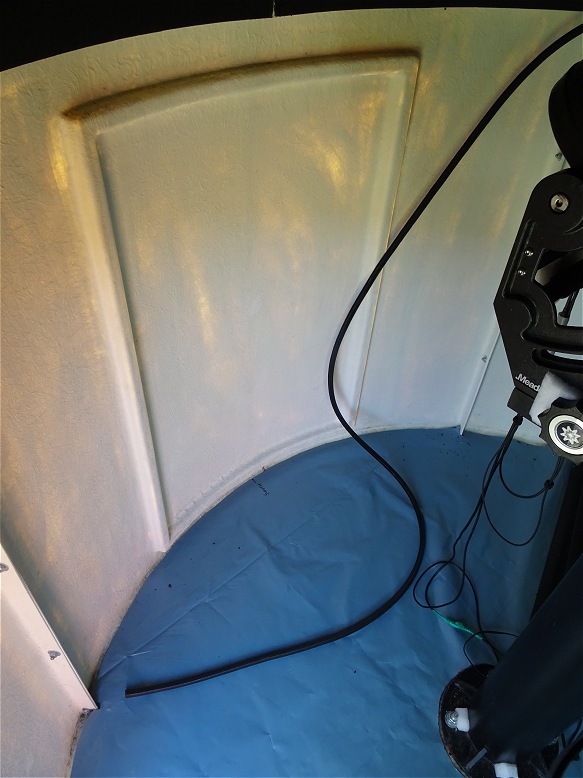 |
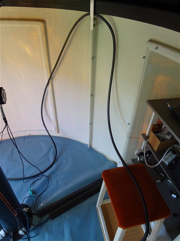 |
|
| Re-securing Rubber Trim with Pair of Pliers (later picture) | ||
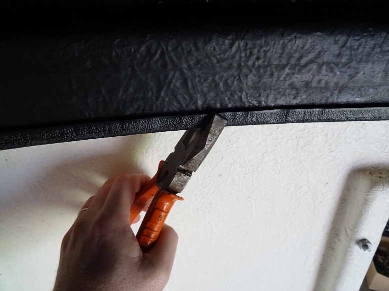 |
||
Back to Top
The original cable conduit for power and USB leads going up to the dome controller, which relied on its sticky tape backing, detached from the observatory wall almost straight after fitting. Attempts since them to seal the cable house to the wall haven't worked for more than a few days at a time. Finally a firmer way of attaching the cable housing in place was developed using a pieces of suitable sized wood, held in place by one of the existing bolts that attach the AllSky/Weather Bay to the Observatory. The cable conduit is now finally held in place in a way that won't come loose..
Pictures showing the new firm attachment for
|
||
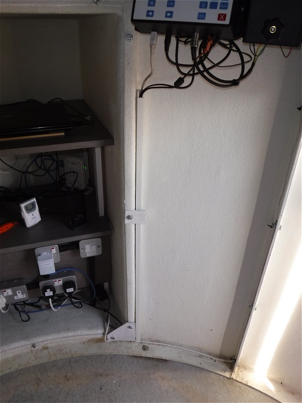 |
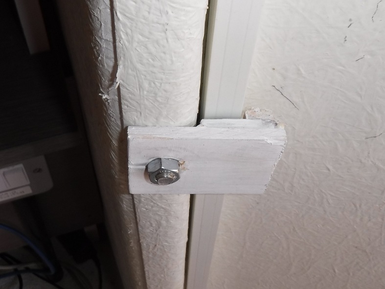 |
|
Back to Top
Following entry of water into observatory during a deluge on 2019-10-18 and a failed first (emergency) attempt at fixing the sealent around the base of the observatory, a second attempt to repair the seal was made a month later on 2019-11-17 / 2019-11-18. It was not easy to find a time to do this in November in November (5 degC 90%+ humidity) when there is a lot of rain and everything remains damp for days on end. However eventually there there was a brief weather window. After stripping out the old sealant , some 24 hours was spent drying out the concrete pad/under wall area. After using tissues to absorb the last bits of water from under the wall and a hair dryer to remove the remaining moisture a fresh bead of sealent was finally applied. This time (hopefully) the repair has done the job. At the least first indications (2019-11-20) are that the leak path has been fixed.
Second Repair Effort (2019-11-18) |
||
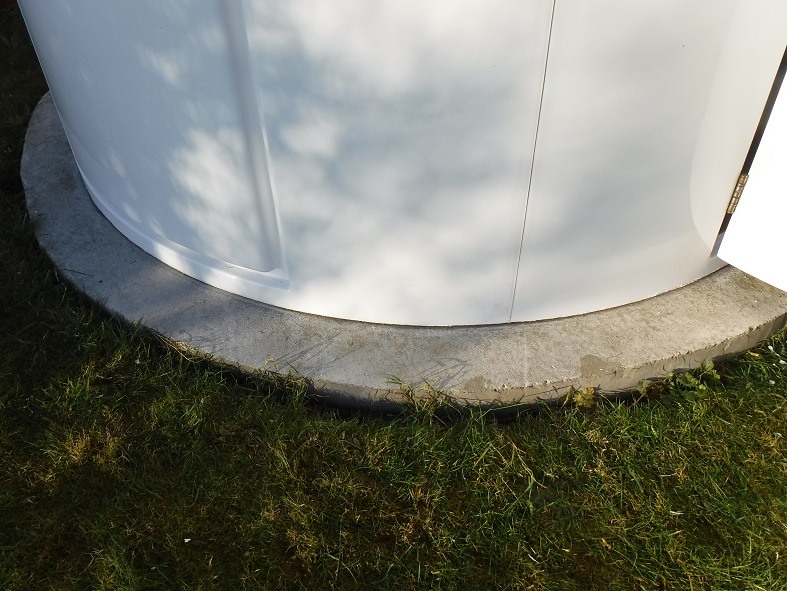 |
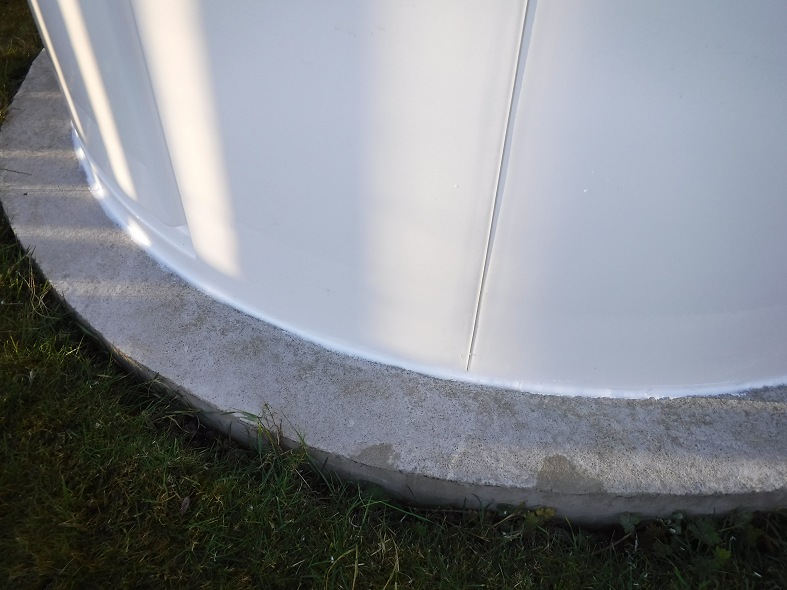 |
|
Observatory Floor (2019-11-20)
|
||
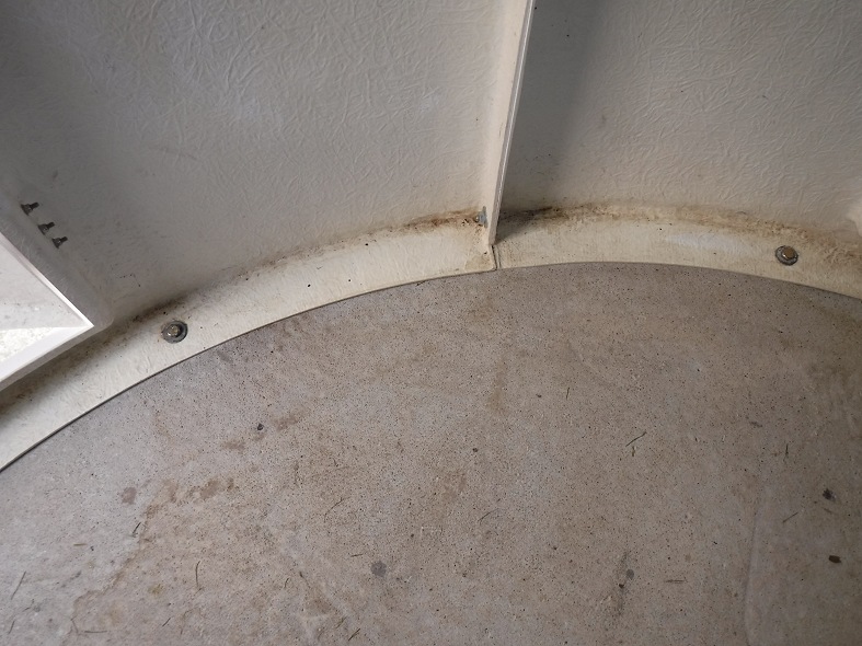 |
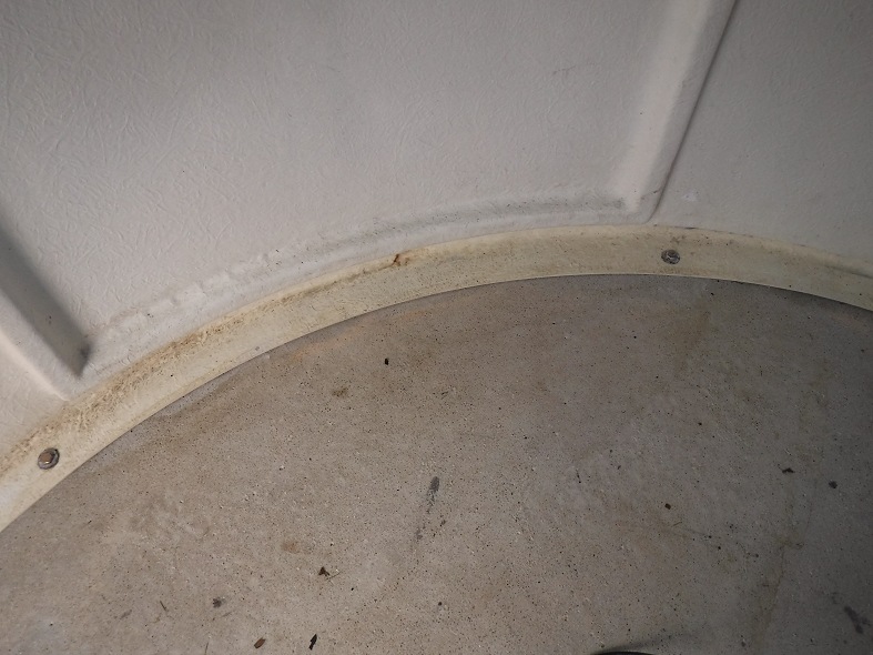 |
|
Follow Up Note (June 2020)
A few months further
on (early 2020) water was again found seeping in from under the walls.
The plastic membrane has been removed and the floor tiles relaid
directly on concrete floor as the membrane was stopping the drying out of the
water in warm weather. A new attempt to seal the walls was made during a dry spell in summer 2020.
Follow Up Note (November 2021)
Water has again been
seeping in from under the walls. This time new sealant was applied on top
of existing sealant and for first time sealant was applied on the inside joint.
See Repair to Observatory
Wall Seals (2021-11-08).
Back to Top
After a full night of observing with the shutter open all night a considerable amount of dew can build up on the inside surfaces of the dome and its shutter. Much of this condensation eventually runs down the inside faces of the dome and accumulates on the flat inside rim particularly in the wide area beneath the shutter and on its counter part on the opposite side of the dome. If the amount of condensation isn't too much it doesn't cause a problem and it eventually evaporates away over the course of several hours (though not without keeping observatory humidity levels high during the process). If there is a lot of condensation the rim puddles can overflow to become floor puddles. Typically the puddle from the beneath the shutter ends up on the floor by the door since the closed shutter intentionally lies over the door when the dome is parked.
Fed up with this situation a number of small holes where made at the backs of the 2 widest areas of the roof rim that will hopefully allow the water of condensation to drain to the exterior of the observatory and reduce the problem inside.
Condensation Puddles on Dome Flange Rim and on Floor |
||
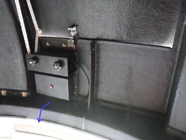 |
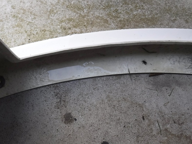 |
|
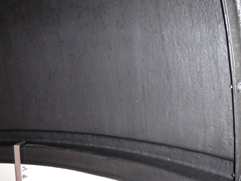 |
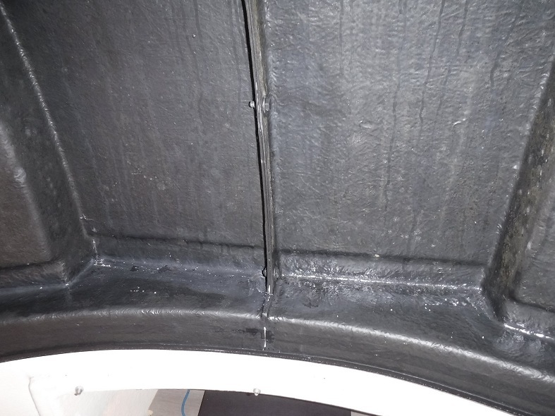 |
|
Drainage holes drilled to help allow condensation puddles to drain to exterior |
||
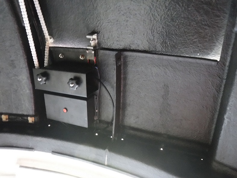 |
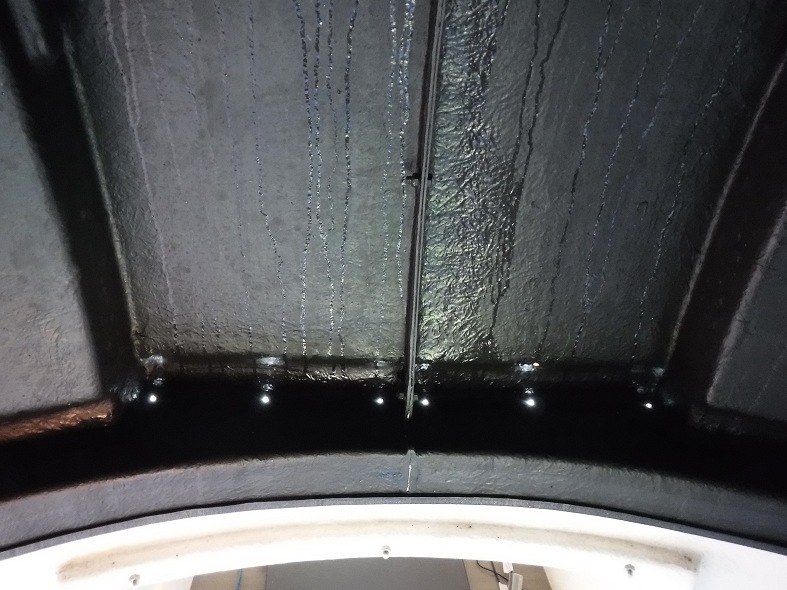 |
|
Update 2019-12-18
After a full night of observing on 2019-12-17 with the shutter open all night and temperatures down to -3°C a fair amount of frost built up on the inside surfaces of the dome and shutter. As this frost melted the next morning lines of of water ran down the inside faces of the dome. Previously this water would accumulate on the flat inside rim particularly in the wide area beneath the shutter and on its counter part on the opposite side of the dome and eventually drip down onto the floor. But since the drilling of a series of drainage holes at the backs of the 2 widest areas of the roof rim last month the water can now gradually drain to the exterior.
Back to Top
During an observing session on 2020-12-17 the shutter was unable to close when clouds developed due to mechanical failure of shutter pulley chain system. Dome left open to potential damage from rain. Shutter opened at 18:24. All logs/reports indicate the shutter had successfully opened (no indication at this time of any problem). Autofocusing conducted and 1st target successfully acquired. After clouds developed at 19:06 the Shutter was automatically commanded to close. An alert was issued saying dome hadn’t closed after 100s (normally takes 45-50s to close). 10 minutes later remote monitoring showed that the dome shutter was still in the 'Closing' state and hadn’t reached the ‘Closed’ state.
After spending a couple of minutes to rule out a problem with the DeviceHub connection, the observatory was visited to check what had happened, where it was found that the shutter drive was still busy turning, but the plastic drive chain had 'delinked' and was no longer attached to the drive cog. The shutter was completely open. In fact the shutter was in a position that was 'over-open' such the U shaped metal limit block (bracket) on the shutter and the chain fixture had been driven beyond their normal range and had overridden the rear roof line ,causing the shutter to be loosely stuck. The chain had come apart adjacent to the point of fixture of the chain to the shutter roof. The shutter was manually closed at 19:26 and a user intervention made to close the session (including parking dome and telescope). The issue was deemed critical as automated operations were unable to close the open shutter and observatory equipment would probably have been damaged by a rain shower that occurred later in the evening at 23:00.
An investigation was made the following day. Although the shutter has
never done this before (multiple open/close operations over last 2.1/2 years) it
was evident with hindsight that this was in fact a problem waiting to happen. It
is noted that the height of the limit block compared to the gap between the
shutter and the roofline means that the limit switch grazes the rounded end of
the limit block rather than hitting the end of the limit block square on.
One link
from the chain was missing and couldn't be found.
It would seem upon opening the dome, the limit switch has been triggered and
the message passed on to dome controller and dome driver, but in this particular
case the rounded end of the limit block had immediately slipped over the limit
switch and over-rode the roofline, causing the shutter to become effectively
‘stuck’. It is supposed that when the command was made to close the dome the
chain delinked due to a combination of the very angle at which the chain rubbed
on the roofline and the excess force required to pull the shutter back from its
‘stuck’ position. Alternatively the chain had delinked when it hit
the roofline when the shutter overran it normal range upon opening.
A repair was made to
the chain by replacing a section of the chain with some spare chain left over
from the original installation
A wood insert was used to raise the height of the limit bracket by 8mm in order to
prevent the issue from ever occuring again.
It was
subsequently learned that Pulsar Observatories space out the limit bracket with
an M8 nut during their own installations, which confirms the fix I had made, but
as of 2020-12-21 the Assembly Manual for Pulsar Dome with Drives on Pulsar
Website was still showing the limit bracket without the necessary space-out.
Back to Top
A new replacememt Home Magnet for Observatory Dome was received from Pulsar
Observatories. This was a replacement for the original magnet that
had become badly corroded and became unreliable for homing the observatory
(photo below left). The original had a cut or flaw in its outer casing and
water had entered the magnet and corroded it over the course of a couple of
years. The new magnet (photo below right).was installed and successfully used
for an overdue recalibration of the dome. The new magnet also allowed ASCOM
Conform tests for the Dome to pass its Find Home Test where it had previously
failed.
| Photo showing the old corroded magnet | Photo showing the new replacement Home Magnet | |
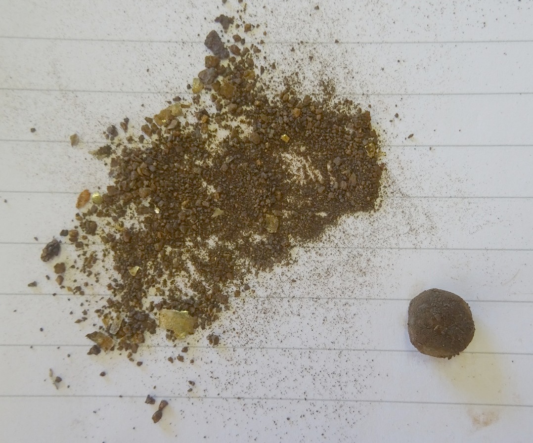 |
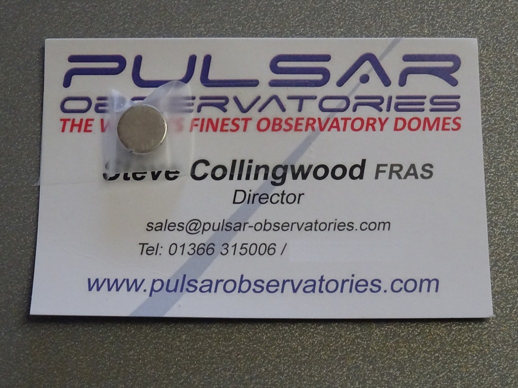 |
|
Update 2021-12-05
New magnet has also begun to
corrode on one side. See image below, casing has fragmented. The Magnet's
magnetic strength seems to be still ok.
| Photo showing the new magnet after 12 months | ||
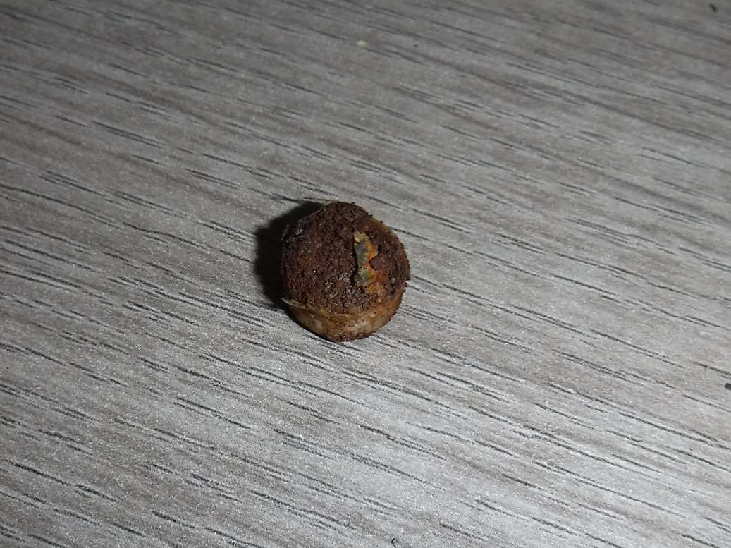 |
||
The Magnet Supplied by Pulsar is a 10mm diameter x 5mm thick, very strong
Neodymium magnet, like these ones from Amazon :
F645-N52-10
Magnet Expert 10mm dia x 5mm thick Ultra High Performance N52 Neodymium Magnet -
3.2kg pull ( Pack of 10 ) by first4magnets™
https://www.amazon.co.uk/Magnet-Expert-thick-Performance-Neodymium/dp/B00GFMQ5OM
(£10.48)
- Corrosion issue is due to basic rusting process (metal/Fe +
water + oxygen).
- The magnet is inevitably exposed to water from
dew/condensation created during nightime observing sessions.
- Neodymium
magnets are apparently known for their poor resistance to corrosion, unless they
are waterproof versions that are coated by a plastic layer or shrink-wrapped in
a PVC cover (which the Pulsar supplied magnets are not)
- The position that
the Home magnet needs to be placed in my system, where it sits in direct contact
with metal embedded in the reinforced rubber trim, might enhance the rate of
corrosion either directly by some electrolysis effect or by causing
damage/scratching to the magnet's 'protective' casing.
- Based on original
supplied magnet, the corrosion will eventually progress to the point that it is
no longer strong enough to be detected by the Dome Unit/Encoder.
Update Q2 2022.
A pack of ten 10mm diameter cylindrical magnets have been
purchased quite cheaply via Amazon for £3.95, and are intended to provide a backup
in case of a future failure of existing magnet. They're only 3mm thick and
only have only 1.2kg pull. Future testing is required to see if they have
sufficiently strength or not.
Update 2022-07-13
The
dome's current Pulsar Supplied home magnet (5mm) was checked today (2022-07-13)
and whilst it has continued to corrode it still works ok for finding the dome's
Home position.
It is likely however that future corrosion will eventually reduce its
magnetic strength to the point that it will now longer be detected by the dome
controller/magnetic reciever, and demands that a working backup is available on
standby.
Tests show that one of the 10mm dia by 3 mm width regular
magnets (purchased earlier this year) doesn't t have sufficient strength to be
detected as a home magnet. However it was found that two of these magnets used
together does have sufficient strength, and can provide a working backup option.
It is possible, but not yet proven, that two regular magnets will have better
corrosion resistance than the Pulsar Supplied Neodymium magnet. See
Home Magnet Tests (2022-07-13)
Back to Top
OpenShutter request at 06:26 failed after 37s with ShutterStatus=5 (Error), whilst a followup OpenShutter request at 06:29 failed after 10s with ShutterStatus=5 (Error). Dome Open/Closing was tested the following day in daylight conditions. The shutter opened ok but the stutters as the shutter/chain connector jumps over the pulley wheels were again very noticeable (as they usually are). Examining the higher guide wheel shown that it has a slight notch worn it to it where the screw head on the shutter/chain connector hits the wheel. It is theorised that the resistance at the guide wheel points, cold temperature and ice combined to cause shutter opening to stall and produce the Shutterstatus=5 (Error). It is assumed that the stall after 37 sec corresponded with the upper guide wheel, whilst the later stall after 10 sec corresponded with lowermost wheel. The higher pulley wheel was rotated to offer a fresh surface for the chain and the Shutter/Chain Connector spacing was adjusted in an attempt to reduce the resistance of the connector coming over the wheels, but there didn't seem to be any improvement.
Pulsar Observatories were contacted for advice (response pending).
|
Photo showing shutter chain passing over upper guide wheel |
Photo showing chain/shutter connector passing over upper guide wheel |
|
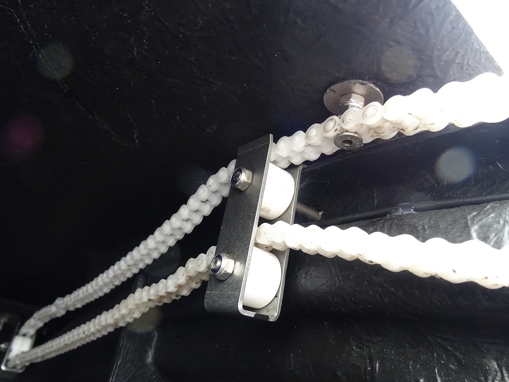 |
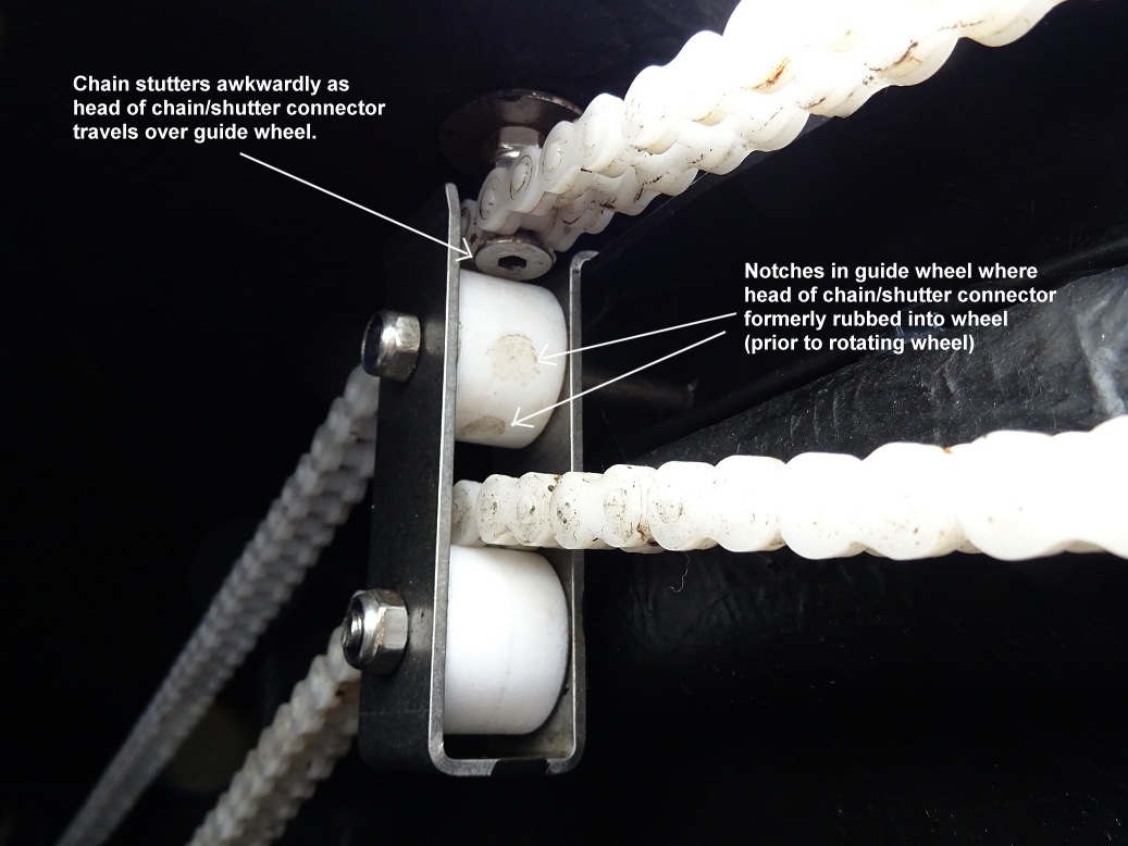 |
|
Back to Top
Following an issue with shutter opening in Session S847 (2021-01-08) (opening failed after 10-27s with ShutterStatus Error=5 and opening stutters/jumps awkwardly when chain bolt goes over guide wheels) and some advice from Pulsar Observations, a couple for adjustments were made to the Observatory's Shutter Chain today (2021-01-15).
Back to Top
Description
With a large amount of rain over the
period 2021-10-28 to 2021-11-01 (see chart below), the observatory
floor became increasing wet and began to rise up through the joints in the
rubber floor matting. The water seeps in under the walls at
places where the white sealant has degraded.
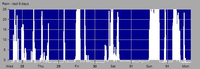
Note: Y Axis is 'rain rate' as measured by Eurotech/Aurora Cloud
Sensor
This has been on ongoing issue since observatory was constructed in 2018 (see Flooded Observatory Floor 2019-10-18), and the seal has been changed out on 2 previous occasions (see Repair to Observatory Base Sealent 2019-11-18). A certain amount of water under the matting can be tolerated but the amount finally become too much and a new repair was required.
Fix
Floor
matts have been removed (2021-11-01) and the excess water removed with
towelling. Floor was allowed to dry out and some emergency
No-Nonsense All Weather Sealant applied as a strip on the outside and (for first time) inside
the wall base in an fresh attempt to try to stop further
water ingress. The sealant is supposedly ''suitable to use in wet weather
conditions". Seals were applied today (2021-11-08). Floor
matts were relaid (2021-11-11) after giving the inside seal opportunity to set.
In past fixes (2019 and 2020) the old seal has been pulled out before
applying new sealant, but since this hasn't proved to be a long term fix in
the past, this time the outside sealant has been applied on top of existing
sealant. Photos below showing the new sealant in place.
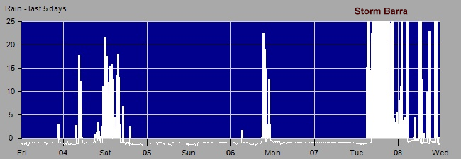
Back to Top
Observatory Shutter failed to fully close during an automated observing
session on 2021-11-09 and was investigated the following day. Dome
was commanded to close when conditons deteriorated, but checking observatory
status 20 minutes later indicated that Shutter was still in the Closing State.
A trip out to the Observatory showed that the lower lip of the Shutter was hung
up on the rubber strip that sits on the lower edge of the aperture leaving the
shutter almost closed but still around 2cm from its fully shut position.
The Shutter drive unit motor had turned itself off, there were no
growling noises coming from it at least (this is good and answers a long
standing question about what happens if the shutter hangs up). Under
manual control the shutter was partially opened using the red button on the
Shutter Drive Unit and then pulling the lower aperture inwards by hand the
shutter was finally closed (again using the red button).
Investigating it is clear that the primary cause of the failure was that
the roof panel below the aperture, to which the shutter drive is attached,
bows out. There is a 1.5cm of play in the panel and it supposed that the
shutter just happened to hang up on this occasion. It has been this
way still its original construction and erection of the observatory in 2018
, but it hasn't presented a problem before now . The dome roof
was constructed on a flat surface and at the time it didn't seem that the 4
four quadrants would fit together without the bulge appearing
and still keep the surfaces of the four
quadrants smooth where they abutted.
Day time pictures that try to
illustrate the failure the previous night are shown below.
A rubber strip is attached to the bottom lip of the aperture. This
does make the lip wider than it would be without it, but even with
this rubber strip the shutter has previously always managed to ride over the
bottom aperture lip and fully close.
Re-reading the Installation
manual I see that it does say "Note that domes with shutter drives
do not have the rubber strip" but I had sufficient length of
rubber strip supplied with the observatory and I used a piece of it on the
lower aperture lip without any problem up to now. I just had to cut out an
appropriate region at the point where the limit switch is positioned.
The manual shows pictures in the Dome Drive section both with and without
this rubber strip being present.
With hindsight this was probably a problem just waiting to happen, but there may be two contributing factors to trigger it on this occasion
Fix/Workaround
I considered various means for either stopping
the aperture lip/panel from bulging outwards so far or would keep the
shutter further away from the lip but couldn't think of anything that would
work (see
more detailed notes). It was decided that the best way of
resolving the issue (or at least minimising the risk of it happening again)
was to remove the rubber strip from the aperture. This was done today
(2021-11-10).
Daytime tests (2021-11-11) indicate that the fix works and observatory operations can continue. The potential of a future hang up is still there since the root cause hasn't been dealt with. Dome closing operations will be therefore be monitored closely over the next two or three sessions to allow confidence in the shutter system to be regained.
Update 2021-12-05
An attempt was made to see if the panel below the lower aperture could be 're-trained' to stay in its correct 'non-bulged' state. A bungee cord was used to pull the panel inwards whilst gentle heat was applied to the panel with a hair-dryer and then left to cool down. The tie was left in place for about one hour. It may or may not have made a slight improvement. The cord was removed after an hour since an observing session was to take place that evening, and the tie cannot be left in place whilst the dome rotates in azimuth. Although it is doubtful that the 'training' will work, further and longer attempts to 'train' the panel will be made over the next few weeks.
Back to Top
The Observatory's Dome (2.2m Pulsar Observatories Dome) is normally operated via an ASCOM Driver that was supplied with the dome in 2018. It's not known whether the driver has been updated since then or not, so the comments below are entirely with reference to the originally supplied driver (“Pulsar Observatories ASCOM Setup.msi”) which has a last modified date of 2017-12-15.
Whilst the driver has been successfully used the driver since 2018 it’s not been without the employment of various workarounds in my observatory control program when it comes to monitoring dome behaviour during slewing and shutter operation. In the current system DeviceHub (an application supplied with the ASCOM installation) provides automated slaved operation of the Pulsar Dome based on the telescope's position / target). This mostly works ok but proper ASCOM based control of the dome can’t be fully achieved without a fix to the Pulsar Driver that would bring it into line with current ASCOM programming standards for domes.
A review identified the following issues with the present driver
This issues have been forwarded to Pulsar Observatories (2022-07-02) with
a request to provide an updated driver, that resolves these issues and
brings the driver into line with current ASCOM programming standards for
Domes.
[ more details
Pulsar
Dome - ASCOM Driver Review, 2022-07-02) ]
Back to Top
A series of tests were carried out on 2022-07-13 in order to understand the functionality of the
Test Screen on the Dome Controller Unit (Settings/Test) and to analyse issues related to
the deployment of the Home Magne (see
Pulsar Dome - Home
Magnet Tests (2022-07-13) . Key findings are given below :-
Test Screen
Home Magnet
Back to Top
The Observatory's dome roof and walls were given a thorough cleaning with warm soapy water. This was to remove dirt and algae that had accumulated since its last major cleaning (2019-09-03). Worst affected areas were the roof & shutter. The northern side of the observatory were most affected by algae. Traces of lichen were also noticed and removed.
Back to Top
During session on 2023-01-16, the shutter was closed and the session suspended ahead of cloud with frequent snow showers. Two hours after the showers had ended (having dropped around 2cm of snow) and after the skies had cleared of cloud the dome was reopened and the session continued with the acquisition of images from 8 further targets. When those images were quickly examined in the morning it was discoved that whilst they contained stars the background had a very uneven illumination pattern. Investigation showed that images appeared this way because of snow / ice on parts of the front lens of the LX200 scope. There was also some snow/ice on front part of the fork, on the left hand fork arm and on two small regions of the observatory floor located either side of the scope. The distribution of ice and the fact that the observatory was closed during the snow showers, strongly suggest that some of the snow/ice that had accumulated on the shutter has slipped and fell into the Observatory when the shutter was opened. Unfortunately the telescope was pointing in a fairly upward direction at the time (pointing to altitude 58°) and some of the snow/ice fell into the dew shield and onto the LX200's corrector lens.
The snow/ice was cleared away from the front of the scope in the morning and dried out. Other snow/ice on the telescope and floor were was collected with brush and pan (before it had a chance to thaw), and removed from observatory.
Whilst the risk of snow/ice entry during shutter opening after snowfall is a known risk,
the mitigation of pointing the telescope in a horizontal direction wasn't
actioned on this occasion (I had just woken up from an alarm I had deliberatlly set and
I was too sleepy at the time to think through the operation / risks).
Whilst putting the telescope into horizontal position wouldn't have prevented
the snow/ice slipping into the observatory, the dew shield would have stopped
that snow/ice getting onto the front of the telescope optics and would thus
allowed the remainder of the imaging session to have been successful rather than a failure.
After battling with continued condensatiion issues despite several attempts
to clear the condensation / humidity from telescope and several sessions with
degraded imaging a Lymax SCT cooler was eventually purchased and used to finally
clear the condensation / humidity on 2023-02-09. This was successful (see
Notes : Lymax SCT Cooler,
2023-02-09).
Back to Top
| This Web Page: | Clair 3 Dome Observatory (2018-2022) |
| Last Updated : | 2024-02-29 |
| Site Owner : | David Richards |
| Home Page : | David's Astronomy Web Site |