David's Astronomy Pages
Notes - Session 1303 (2025-03-18)
Notes
(S1302)
Notes
Main
Home
Page
Notes
(S1304)
David's Astronomy Pages
|
Notes (S1302) |
Notes Main |
Home Page |
Notes (S1304) |
Main aims
Equipment & Software
Highlights
Summary Plots & Logs
Observing Plan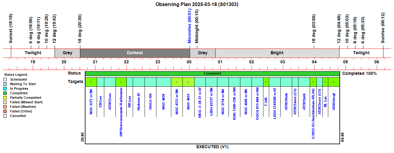 |
||||||||||||||||||||||||||||||||||||||||||||||||||||||||||||||||||||||||||||||||||||||||||||||||||||||||||||||||||||||||||||||||||||||||||||||||||||||||||||||||||||||||||||||||||||||||||||||||||||||||||||||||||||||||||||||||||||||||||||||||||||||||||||||||||||||||||||||||||||||||||||||||||||||||||||||||||||||||||||||||||||||||||||||||||||||||||||||||||||||||||||||||||||||||||||||||||||||||||||||||||||||||||||||||||||||||||||||||||||||||||||||||||||||||||||||||||||||||||||||||||||||||||||||||||||||||||||||||||||||||||||||||||||||||
|
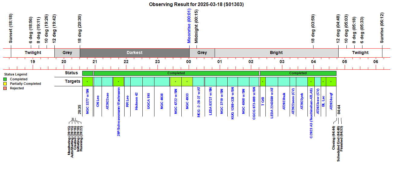
Observing Result |
||||||||||||||||||||||||||||||||||||||||||||||||||||||||||||||||||||||||||||||||||||||||||||||||||||||||||||||||||||||||||||||||||||||||||||||||||||||||||||||||||||||||||||||||||||||||||||||||||||||||||||||||||||||||||||||||||||||||||||||||||||||||||||||||||||||||||||||||||||||||||||||||||||||||||||||||||||||||||||||||||||||||||||||||||||||||||||||||||||||||||||||||||||||||||||||||||||||||||||||||||||||||||||||||||||||||||||||||||||||||||||||||||||||||||||||||||||||||||||||||||||||||||||||||||||||||||||||||||||||||||||||||||||||||
 |
||||||||||||||||||||||||||||||||||||||||||||||||||||||||||||||||||||||||||||||||||||||||||||||||||||||||||||||||||||||||||||||||||||||||||||||||||||||||||||||||||||||||||||||||||||||||||||||||||||||||||||||||||||||||||||||||||||||||||||||||||||||||||||||||||||||||||||||||||||||||||||||||||||||||||||||||||||||||||||||||||||||||||||||||||||||||||||||||||||||||||||||||||||||||||||||||||||||||||||||||||||||||||||||||||||||||||||||||||||||||||||||||||||||||||||||||||||||||||||||||||||||||||||||||||||||||||||||||||||||||||||||||||||||||
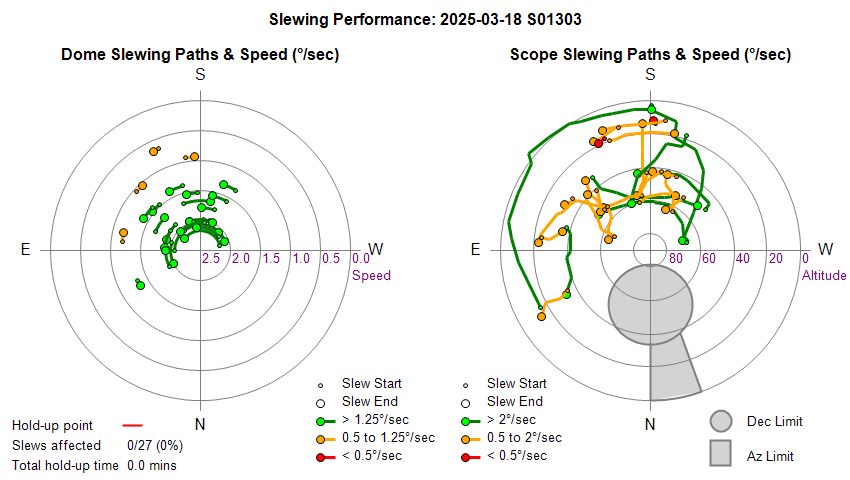
| Dome & Scope Slewing Performance | ||||||||||||||||||||||||||||||||||||||||||||||||||||||||||||||||||||||||||||||||||||||||||||||||||||||||||||||||||||||||||||||||||||||||||||||||||||||||||||||||||||||||||||||||||||||||||||||||||||||||||||||||||||||||||||||||||||||||||||||||||||||||||||||||||||||||||||||||||||||||||||||||||||||||||||||||||||||||||||||||||||||||||||||||||||||||||||||||||||||||||||||||||||||||||||||||||||||||||||||||||||||||||||||||||||||||||||||||||||||||||||||||||||||||||||||||||||||||||||||||||||||||||||||||||||||||||||||||||||||||||||||||||||||||
 |
||||||||||||||||||||||||||||||||||||||||||||||||||||||||||||||||||||||||||||||||||||||||||||||||||||||||||||||||||||||||||||||||||||||||||||||||||||||||||||||||||||||||||||||||||||||||||||||||||||||||||||||||||||||||||||||||||||||||||||||||||||||||||||||||||||||||||||||||||||||||||||||||||||||||||||||||||||||||||||||||||||||||||||||||||||||||||||||||||||||||||||||||||||||||||||||||||||||||||||||||||||||||||||||||||||||||||||||||||||||||||||||||||||||||||||||||||||||||||||||||||||||||||||||||||||||||||||||||||||||||||||||||||||||||
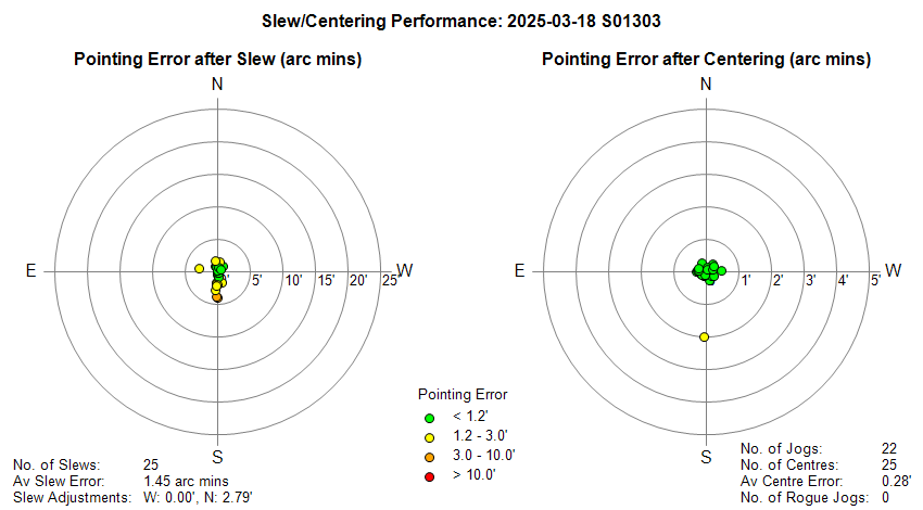
| Slew/Centering Performance | ||||||||||||||||||||||||||||||||||||||||||||||||||||||||||||||||||||||||||||||||||||||||||||||||||||||||||||||||||||||||||||||||||||||||||||||||||||||||||||||||||||||||||||||||||||||||||||||||||||||||||||||||||||||||||||||||||||||||||||||||||||||||||||||||||||||||||||||||||||||||||||||||||||||||||||||||||||||||||||||||||||||||||||||||||||||||||||||||||||||||||||||||||||||||||||||||||||||||||||||||||||||||||||||||||||||||||||||||||||||||||||||||||||||||||||||||||||||||||||||||||||||||||||||||||||||||||||||||||||||||||||||||||||||||
 |
||||||||||||||||||||||||||||||||||||||||||||||||||||||||||||||||||||||||||||||||||||||||||||||||||||||||||||||||||||||||||||||||||||||||||||||||||||||||||||||||||||||||||||||||||||||||||||||||||||||||||||||||||||||||||||||||||||||||||||||||||||||||||||||||||||||||||||||||||||||||||||||||||||||||||||||||||||||||||||||||||||||||||||||||||||||||||||||||||||||||||||||||||||||||||||||||||||||||||||||||||||||||||||||||||||||||||||||||||||||||||||||||||||||||||||||||||||||||||||||||||||||||||||||||||||||||||||||||||||||||||||||||||||||||
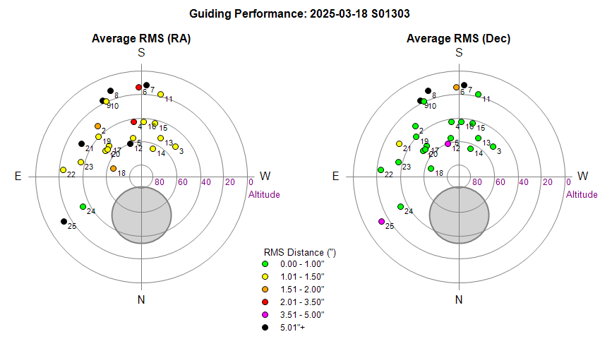
| Guiding Performance | ||||||||||||||||||||||||||||||||||||||||||||||||||||||||||||||||||||||||||||||||||||||||||||||||||||||||||||||||||||||||||||||||||||||||||||||||||||||||||||||||||||||||||||||||||||||||||||||||||||||||||||||||||||||||||||||||||||||||||||||||||||||||||||||||||||||||||||||||||||||||||||||||||||||||||||||||||||||||||||||||||||||||||||||||||||||||||||||||||||||||||||||||||||||||||||||||||||||||||||||||||||||||||||||||||||||||||||||||||||||||||||||||||||||||||||||||||||||||||||||||||||||||||||||||||||||||||||||||||||||||||||||||||||||||
 |
||||||||||||||||||||||||||||||||||||||||||||||||||||||||||||||||||||||||||||||||||||||||||||||||||||||||||||||||||||||||||||||||||||||||||||||||||||||||||||||||||||||||||||||||||||||||||||||||||||||||||||||||||||||||||||||||||||||||||||||||||||||||||||||||||||||||||||||||||||||||||||||||||||||||||||||||||||||||||||||||||||||||||||||||||||||||||||||||||||||||||||||||||||||||||||||||||||||||||||||||||||||||||||||||||||||||||||||||||||||||||||||||||||||||||||||||||||||||||||||||||||||||||||||||||||||||||||||||||||||||||||||||||||||||
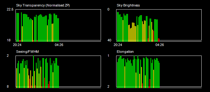
| Sky Conditions (Locate Frames) | ||||||||||||||||||||||||||||||||||||||||||||||||||||||||||||||||||||||||||||||||||||||||||||||||||||||||||||||||||||||||||||||||||||||||||||||||||||||||||||||||||||||||||||||||||||||||||||||||||||||||||||||||||||||||||||||||||||||||||||||||||||||||||||||||||||||||||||||||||||||||||||||||||||||||||||||||||||||||||||||||||||||||||||||||||||||||||||||||||||||||||||||||||||||||||||||||||||||||||||||||||||||||||||||||||||||||||||||||||||||||||||||||||||||||||||||||||||||||||||||||||||||||||||||||||||||||||||||||||||||||||||||||||||||||
 |
||||||||||||||||||||||||||||||||||||||||||||||||||||||||||||||||||||||||||||||||||||||||||||||||||||||||||||||||||||||||||||||||||||||||||||||||||||||||||||||||||||||||||||||||||||||||||||||||||||||||||||||||||||||||||||||||||||||||||||||||||||||||||||||||||||||||||||||||||||||||||||||||||||||||||||||||||||||||||||||||||||||||||||||||||||||||||||||||||||||||||||||||||||||||||||||||||||||||||||||||||||||||||||||||||||||||||||||||||||||||||||||||||||||||||||||||||||||||||||||||||||||||||||||||||||||||||||||||||||||||||||||||||||||||
|
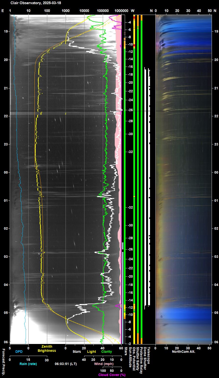
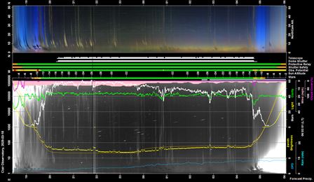
Night Sky Summary Plot Top axis: Sky Brightness at Zenith (in ADU/s) Lefthand axis: Local Time (hh LT). Righthand axis: Sun Altitude (degs) |
||||||||||||||||||||||||||||||||||||||||||||||||||||||||||||||||||||||||||||||||||||||||||||||||||||||||||||||||||||||||||||||||||||||||||||||||||||||||||||||||||||||||||||||||||||||||||||||||||||||||||||||||||||||||||||||||||||||||||||||||||||||||||||||||||||||||||||||||||||||||||||||||||||||||||||||||||||||||||||||||||||||||||||||||||||||||||||||||||||||||||||||||||||||||||||||||||||||||||||||||||||||||||||||||||||||||||||||||||||||||||||||||||||||||||||||||||||||||||||||||||||||||||||||||||||||||||||||||||||||||||||||||||||||||
 |
||||||||||||||||||||||||||||||||||||||||||||||||||||||||||||||||||||||||||||||||||||||||||||||||||||||||||||||||||||||||||||||||||||||||||||||||||||||||||||||||||||||||||||||||||||||||||||||||||||||||||||||||||||||||||||||||||||||||||||||||||||||||||||||||||||||||||||||||||||||||||||||||||||||||||||||||||||||||||||||||||||||||||||||||||||||||||||||||||||||||||||||||||||||||||||||||||||||||||||||||||||||||||||||||||||||||||||||||||||||||||||||||||||||||||||||||||||||||||||||||||||||||||||||||||||||||||||||||||||||||||||||||||||||||
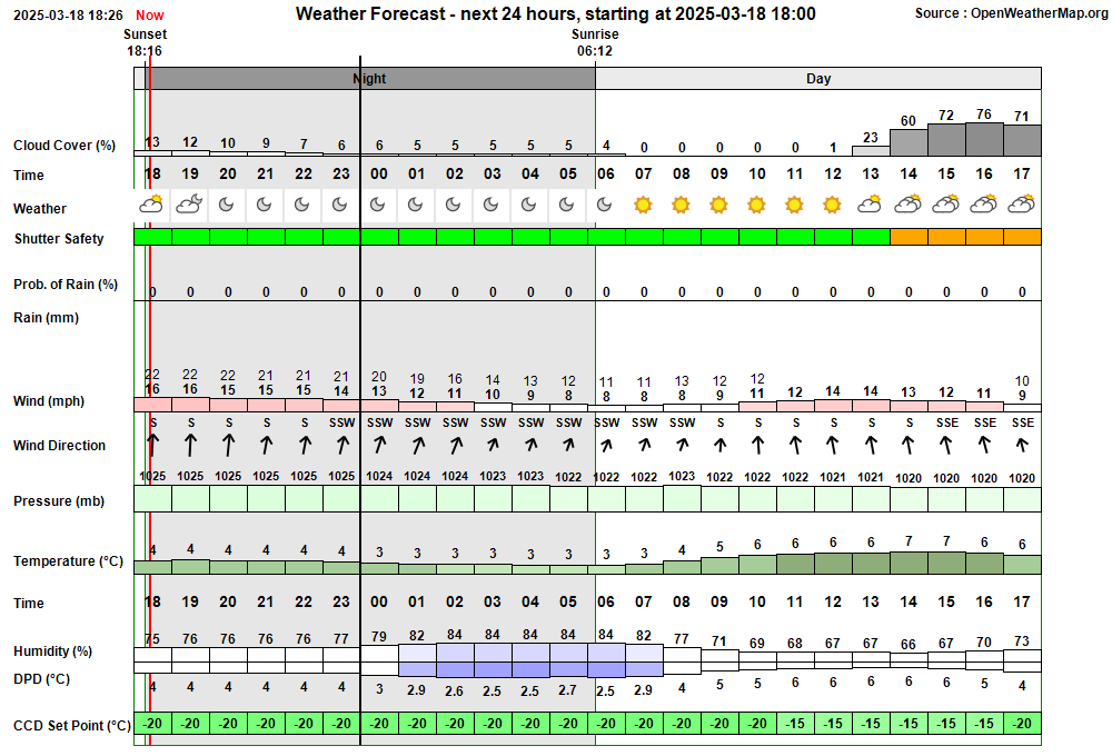
| Actual Weather vs Pre-Session Weather Forecast | ||||||||||||||||||||||||||||||||||||||||||||||||||||||||||||||||||||||||||||||||||||||||||||||||||||||||||||||||||||||||||||||||||||||||||||||||||||||||||||||||||||||||||||||||||||||||||||||||||||||||||||||||||||||||||||||||||||||||||||||||||||||||||||||||||||||||||||||||||||||||||||||||||||||||||||||||||||||||||||||||||||||||||||||||||||||||||||||||||||||||||||||||||||||||||||||||||||||||||||||||||||||||||||||||||||||||||||||||||||||||||||||||||||||||||||||||||||||||||||||||||||||||||||||||||||||||||||||||||||||||||||||||||||||||
 |
||||||||||||||||||||||||||||||||||||||||||||||||||||||||||||||||||||||||||||||||||||||||||||||||||||||||||||||||||||||||||||||||||||||||||||||||||||||||||||||||||||||||||||||||||||||||||||||||||||||||||||||||||||||||||||||||||||||||||||||||||||||||||||||||||||||||||||||||||||||||||||||||||||||||||||||||||||||||||||||||||||||||||||||||||||||||||||||||||||||||||||||||||||||||||||||||||||||||||||||||||||||||||||||||||||||||||||||||||||||||||||||||||||||||||||||||||||||||||||||||||||||||||||||||||||||||||||||||||||||||||||||||||||||||
| Session Event Log | ||||||||||||||||||||||||||||||||||||||||||||||||||||||||||||||||||||||||||||||||||||||||||||||||||||||||||||||||||||||||||||||||||||||||||||||||||||||||||||||||||||||||||||||||||||||||||||||||||||||||||||||||||||||||||||||||||||||||||||||||||||||||||||||||||||||||||||||||||||||||||||||||||||||||||||||||||||||||||||||||||||||||||||||||||||||||||||||||||||||||||||||||||||||||||||||||||||||||||||||||||||||||||||||||||||||||||||||||||||||||||||||||||||||||||||||||||||||||||||||||||||||||||||||||||||||||||||||||||||||||||||||||||||||||
|
||||||||||||||||||||||||||||||||||||||||||||||||||||||||||||||||||||||||||||||||||||||||||||||||||||||||||||||||||||||||||||||||||||||||||||||||||||||||||||||||||||||||||||||||||||||||||||||||||||||||||||||||||||||||||||||||||||||||||||||||||||||||||||||||||||||||||||||||||||||||||||||||||||||||||||||||||||||||||||||||||||||||||||||||||||||||||||||||||||||||||||||||||||||||||||||||||||||||||||||||||||||||||||||||||||||||||||||||||||||||||||||||||||||||||||||||||||||||||||||||||||||||||||||||||||||||||||||||||||||||||||||||||||||||
| Session Alerts & Alarms | ||||||||||||||||||||||||||||||||||||||||||||||||||||||||||||||||||||||||||||||||||||||||||||||||||||||||||||||||||||||||||||||||||||||||||||||||||||||||||||||||||||||||||||||||||||||||||||||||||||||||||||||||||||||||||||||||||||||||||||||||||||||||||||||||||||||||||||||||||||||||||||||||||||||||||||||||||||||||||||||||||||||||||||||||||||||||||||||||||||||||||||||||||||||||||||||||||||||||||||||||||||||||||||||||||||||||||||||||||||||||||||||||||||||||||||||||||||||||||||||||||||||||||||||||||||||||||||||||||||||||||||||||||||||||
|
||||||||||||||||||||||||||||||||||||||||||||||||||||||||||||||||||||||||||||||||||||||||||||||||||||||||||||||||||||||||||||||||||||||||||||||||||||||||||||||||||||||||||||||||||||||||||||||||||||||||||||||||||||||||||||||||||||||||||||||||||||||||||||||||||||||||||||||||||||||||||||||||||||||||||||||||||||||||||||||||||||||||||||||||||||||||||||||||||||||||||||||||||||||||||||||||||||||||||||||||||||||||||||||||||||||||||||||||||||||||||||||||||||||||||||||||||||||||||||||||||||||||||||||||||||||||||||||||||||||||||||||||||||||||
Back to Top
Back to Top Issue, Back to Top
Fig 1. Foc2 Focus Profile (wide)
Fig 2. Foc2 Focus Profile which was rejected due to "Quadratic values indicate poor/invalid profile"
Back to Top Issue, Back to Top
A Geomagnetic Monitoring Station is being added to the Observatory in Spring 2025 for monitoring changes in the earth's magnetic field and to supplement and build upon the Observatory's existing Aurora monitoring using AllSky Camera and new NorthCam Camera.
The following notes describe the SAM III Arrival and Initial
Examinations.
Other Notes:
|
Review | SAM III |
Site Prep |
Assembly
Design |
Parts
Assembly | Testing
|
Final Assembly |
Installation
|
Commissioning |
Remedial
Fix |
Operation |
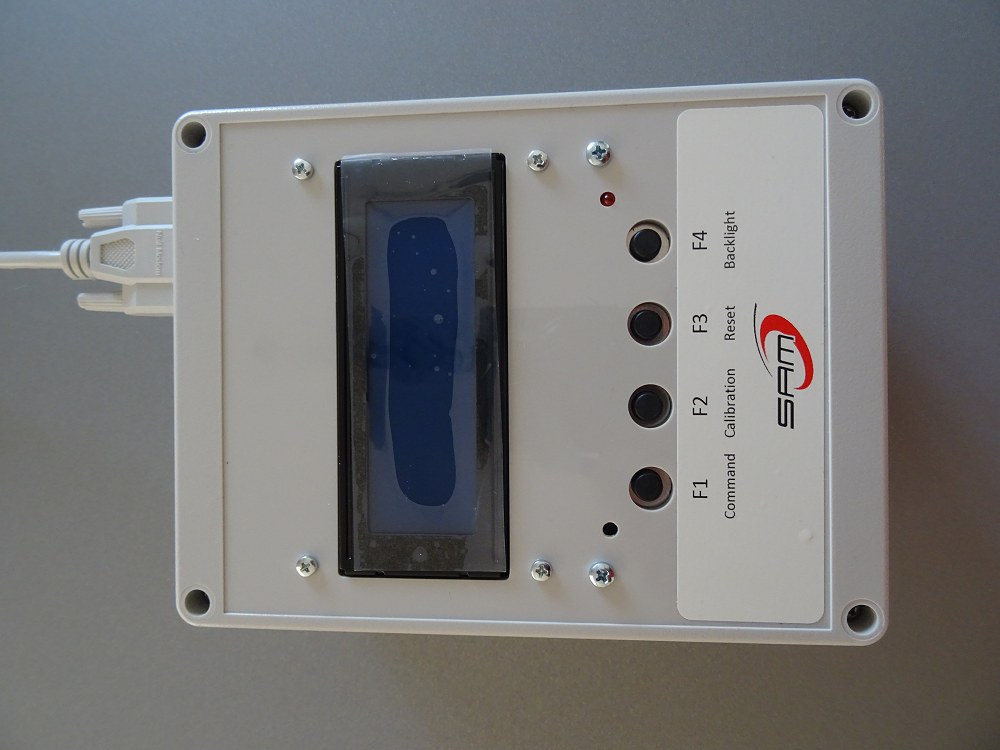
SAM III Arrival (2025-03-18)
SAM III Order arrived today (2025-03-18) and installation plan is being
developed.
Questions:
Q. How are cable wires fitted to the SAM III Controller Box.
A.
Bared ends of wires are inserted into appropriate slots in the green
10-position pluggable terminal block X2. , and screws tightened.
After double checking that correct wires are in their correct slots, insert
green adapter bars in port on SAM III controller box
1 GND X
2 Signal X
3 +5Vdc X
4
GBD Y
5 Signal Y
6 +5Vdc Y
7 GBD Y
8 Signal Y
9 +5Vdc
Y
10 Not used.
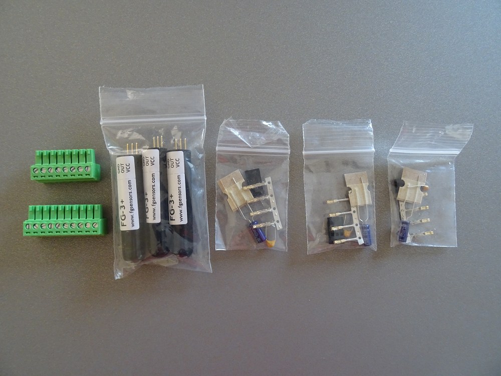
Q. Identifying Cables to/from Sensor Sensors ?
Three CAT6 cables should
be clearly identified at both ends, marked X, Y, Z according to which
axis they will each be connected to.
Q. A standard 'scheme' should be defined to detail the particular
wires in the CAT6 cable that will be used for connecting to the GND, OUT and VCC pins
on the FG-3+ sensors and to the relevant slots on the Controller Box.
GND - Blue Wire = Ground
OUT - Orange Wire = Sensor
output
VCC - Brown Wire = +5 V Power
Q. How to ensure that water can't enter to the Piped Sensor Unit at
the point of cable entry. (3 Cat6 cables and 1 temperature cable)
A.
Inverted U Tube ?, Expoxy Filler,
Q. How to build 'cage' for mounting the
three FG-3+ sensors.
A. Circular Wood Cage ? , 3D
Printed Cages from Torc ?,
Q. How to wire up the FG-3+ sensors
(including 10 µF, 25 V tantalum
capacitor & 100 nF 25 V multi-layer ceramic capacitor ) ?
A. Refer to wiring plan in manual
Q.
How to connect wires
to 3 pin adapter using metal tags. How are the metal tag inserted into
plastic adapter ?
A. From Installation Guide:
A 3-pin
single inline header connector and contacts are supplied for connecting
cable to each sensor. Crimp or solder the sensor cable wires to the contacts
and insert them in the SIL header connector. The SIL header connector has
slots on one side, and the tiny tabs on the contacts must be inserted on
this side. Do not solder wires directly to the sensor. The sensor pinout is
indicated on the sensor label and in the drawings below.
The socket
contacts require a double-crimp, one for the conductor and one for the
insulation. If you do not have a crimping tool and must solder the wires, it
is suggested you cut the insulation crimp fingers off of the contact
(otherwise, it is unlikely you can fold the fingers enough to make them fit
the header connector). You will need to fold the conductor crimp with a pair
of miniature pliers. Do this very carefully to avoid damaging the contact.
Apply a very small amount of solder – if you apply too much solder it will
wick up into the socket.
Before inserting the single inline (SIL)
header onto the sensor pins, put a small amount of dielectric grease (for
example, Permatex 81150 available at most automotive parts stores) on the
sensor pins. The amount of grease used should be small enough that it is not
visible on the pins. This will help prevent corrosion if the sensor is used
in outdoor applications. The header has no built-in polarity indicator so it
should be marked with nail polish, paint or tape to indicate proper
orientation.
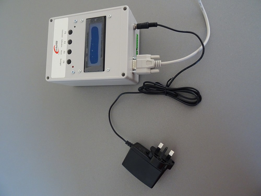
Q. Does the existing 12mm Male Plug from the A/C Power Adapter Unit
need to be replaced with either the longer 14mm plug or with 12mm plug with
locking nut. ?
A. Controller Unit was tested with existing 12mm
Male Plug and it initialises ok. A disconnection/reconnection occurs
if the plug is physically rotated, but not under general use. It seems
secure enough.
( I'd rather not change the plug as this requires cutting
off the existing male plug and soldering/crimping wires to the new plug and
then rely on screwed connection on working loose.)
Q. How should the X, Y & Z Geomagnetometer Sensors be orientated
?
A. As per construction manual
X
North-South , pins SOUTH
Y
East-West, pins WEST
Z Vertical,
pins UP
Q. What entries should be made in the SAM_VIEW setup/settings ?
A. Settings
Owner or Station Name :
Clair Observatory
Location :
Ellon, Scotland
Longitude, Latitude
02.00W, 57.32N
IARU-Locator :
IO87xh
Q. What are expected 3-axis field strengths ?
A.
Using the calculator at
World Magnetic Model 2025 Calculator (geomag.bgs.ac.uk) the expected
field strengths at the Observatory for 2025-04-01.
X:
16467nT (4.4 nT/year)
Y:
-100 nT (59.1 nT/year)
Z: 47326 nT (32.8 nT/year)
H : 16468 nT (4.0 nT/year) (Horizontal
Intensity, from X & Y vector sum)
F : 50110
nT (32.3 nT/year) (Total
Intensity)
D : -0.348 deg East
(12.4 arc min/year)
I : 70.814 deg
Incl'n (0.5 arc min/year) ' Angle from Horizontal
- See
also
What are the
geomagnetic components ? (intermagnet.org)
Q. What is the geomagnetic latitude of the Station
A.
54.36° N
From IGRF, At Epoch 2025.0 Lat 57.32 N, Long -2.00 E, the
Quasi-Dipole Latitude is 53.36° (vs Dipole Latitude 59.26°)
Q. Cross-Talk Issue / Potential Solutions ?
A. Watch
talk by Whitham Reeve (YouTube :
https://www.youtube.com/watch?v=0TXE-hZ5kuU )
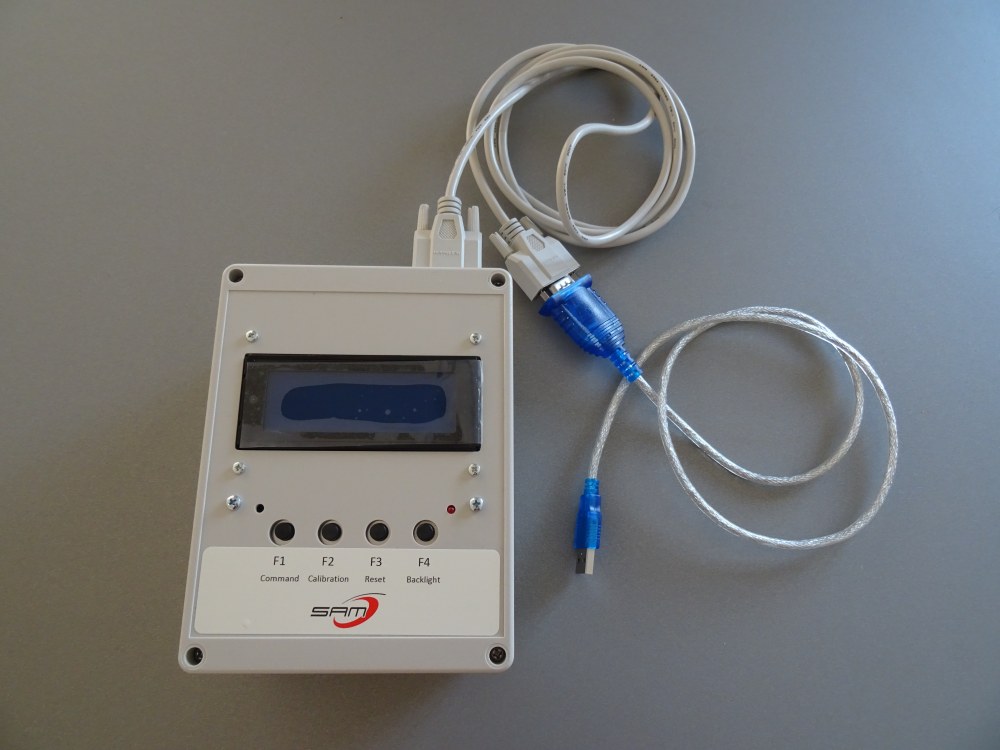
SAM III - PC Connection (2025-03-19)
- Created program folder 'C:\More Programs\SAM'
and copy into the folder the files from
'..\Software-Firmware\SAM3 Applications'
'..\Software-Firmware\Runtime Libraries'
- Installed SABRENT USB-Serial Driver
. CD ..
/Windows/PL23XX_Prolific_DriverInstaller_v301-WIN11/PL23XX-M_LogoDriver_Setup_v301_20211221.exe
- Used PL23XX_checkChipVersion_v1020.exe' to check
'COM4' this gave the meessage :
"This is a PL-2303 GS chip"
- Made a trial connection to SAM III unit
- Connect USB-Serial
Cable to Computer
- Appears as "Prolific PL2303GS USB Serial Com
Port (COM4)
(COM4 on Development/Analysis Computer)
- Connect USB-Serial Cable
between Computer and SAM III box via Serial Pass Through Cable)
- Opened SAM_INI_v2-0.exe
- Selected COM Port (COM 4)
- Set default
values used to confirm values on Form are defaults.
(proven by
changing a value and then using Set Default Values to see it overwrite the
manually changed value)
- Tried 'Send parameters'.
After running to 100%, 'Error!' dialog shown with message "Error while
writing parameter set!"
Tried 'Receive parameters'
After running to 100%, 'Error!' dialog shown with message "Error while
reading parameter set!"
A Port Monitor confirms that data
is coming from the SAM Unit with data every second, like
20.03.25
15:57:01: X,,Y,,Z,
-If SAM_INI_v2.0 is opened and connected to COM4 with the SAM III in
command mode (F1) and
'Send Parameters' is used, SAM_INI runs to c. 50%
and then displays message "SAM does not respond".
- Trying again :
'Receive
Parameters' , trackbar runs to 100% and message 'Parameter read
successful.." appears
Trying again
'Send Parameters' :
trackbar runs to 100% and message 'Parameter write successful.."
appears
After a successful 'Write', the SAM box
automatically resets itself.
To do:
- Dig a 120 cm deep hole to contain 3-axis
geomagnetometer sensor fixture (see Update 2025-03-23 to
Updates 2025-03-25 below)
- Prepare 3 CAT6 cables, one cable for each sensor
- Prepare Temperature Monitor (see
DS18B20 Waterproof Digital Temperature Sensor (2025-03-19)
|
Review | SAM III |
Site Prep |
Assembly
Design |
Parts
Assembly | Testing
|
Final Assembly |
Installation
|
Commissioning |
Remedial
Fix |
Operation |
Back to Top
| This Web Page: | Notes - Session 1303 (2025-03-18) |
| Last Updated : | 2025-07-04 |
| Site Owner : | David Richards |
| Home Page : | David's Astronomy Web Site |
