David's Astronomy Pages
Notes - New Observatory Plan (2018)
Observatory
Notes
Main
Home
Page
Notes
(S607)
David's Astronomy Pages
|
Observatory |
Notes Main |
Home Page |
Notes (S607) |
After using my roof-off roof observatory for some 21 years (used at 3 different sites) and struggling with it in the past couple of years I've decided that I need to get a completely new observatory in 2018. The plan is to get a 2.2m dome observatory with rotation and shutter drives, but the project is still subject to spousal permission / negiotiation. The observatory would be placed on either a square, octagonal or circular concrete pad. Justification and aims for the New Observatory are listed in a following section.
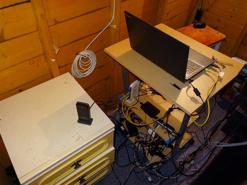
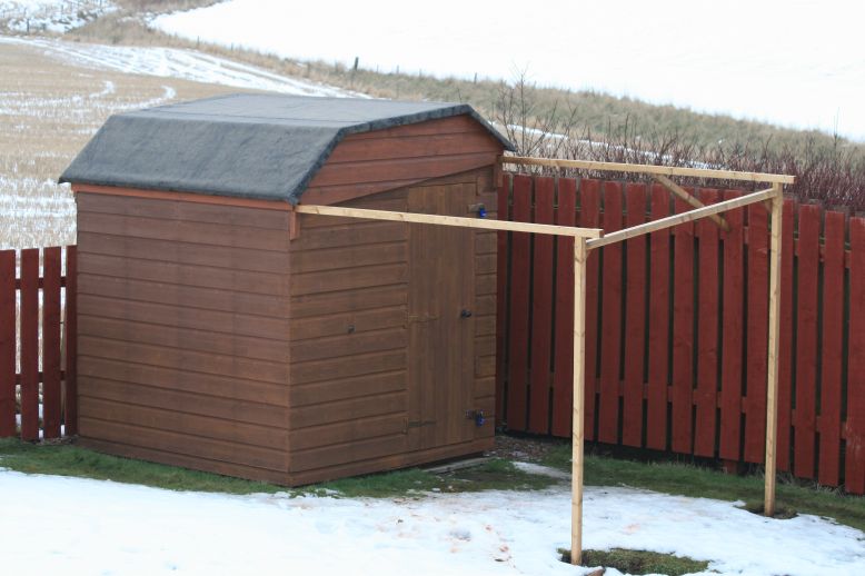
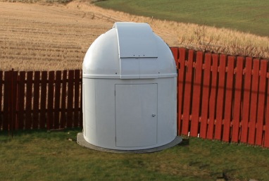
| Current Roll-Off Roof Observatory | Mock-Up View of New Observatory | |
 |
 |
Back to Top
1) Resolve 5 specific issues associated with my current roll-off roof observatory:
- difficulties in opening/closing current observatory roof
(roof is increasingly difficult to move due to gradual warping of the two
sides, causing wheels to fall off the wall rails)
- safety
issues associated with opening/closing 'stiff' roof (potential for back, shoulder or
hamstring injury)
- safety issue associated with deterioration
(rot) in one of the roll-off support stands (potential for crush injuries if
roof collapses)
- buffetting of telescope by wind with
consequential poor imaging in anything more than a light breeze
(buffetting problems were magnified in 2009 when a new roof-off was built and
a new larger scope (12" LX200) was installed
this had the
combined affect of exposing the telescope to more wind which has reduced the
quality of certain data and
reduced the number of nights
when the scope can be operated)
- gradual deterioration (rot)
& water ingress in parts of the 20 year old shed frame
2) Provide
additional capability and
opportunities from a new dome observatory:
- increase astronomical observing/imaging time, by being easier to
operate and being less sensitive to weather conditions
- allow
secondary scope & camera to remain attached to the main telescope between
sessions making setup quicker and more reliable (at present the secondary scope & camera has
to be mounted, connected, disconnected & dismounted at each session)
- reduce
number and length of visits to the observatory by increasing remote
operation capability (e.g. opening/closing roof remotely)
-
opportunity to improve observatory electrics, wiring, cabling, communications
and lighting
- provide a robust weather resistant structure requiring
less maintainence.
3) Help meet specific future observing plans
-
exoplanet transits
- high resolution planetary imaging
- solar observing
Back to Top
The outline plan for the new Dome Observatory is to site it in approximately the same location as the existing Roll-Off Roof Observatory, but offset it slightly to allow for a new pier base and to position it slightly further from boundary fencing. I expect to reuse the existing Power Supply Line. A plan view illustration is shown below (Note that precise offset from existing observatory, precise southerly pier offset from dome centre and the positions of the observatory door and a planned single bay are still to be finalised).
| Outline Plan for New Observatory |
 |
Plan is to buy a 2.2m Full Height Dome Observatory from Pulsar Observatories
( https://www.pulsarastro.com/ )
including key accessories such as Rotation and Shutter Drives.
Back to Top
Outline project plan is as follows:
- Decide key specifications (1 or 2 bays) & budget
- Agreement to proceed
- Order 2.2m dome observatory & associated
accessories from Pulsar
Observatories for delivery in spring 2018
- Consult an Electrician regarding
observatory power supply & power panel for new observatory.
- Remove existing
observatory (including removal of roll-off supports & metal pier)
- Reduce
the height of current metal pier (contract local metal fabricator/blacksmith)
- Dig hole for new pier base and footings for the observatory's concrete pad
- Build and install levelled former for pier block & concrete pad.
- Pour
concrete into pier hole and the former & level off (contract local concrete
supply & delivery firm)
- Receive dome observatory and self install (with
help from son)
- Drill holes in Concrete Pier Base, Install Bolts and Install
pier
- Install power panel & hook up (contract Electrician where required)
Back to Top
|
Pier Block (Old concrete pier block may cause physical problems during the construction of a new pier block) |
|
|
GPS Fix (LX200 may be unable to get GPS fix (including accurate time) at start up and may hang) |
|
|
Dome Aperture (Main and/or secondary scope might not be able to see out through the Dome Aperture when pointing in particular directions, such as close to zenith |
|
|
Condensation (Condenation might be a problem in dome observatory with deterimental imapct on equipment etc) |
|
|
Power Overloading (Power requirements including new equipment might exceed 13A fuse rating on the main plug serving the observatory) |
1) Observatory Size. Whilst the current and the planned new
observatory are both predominantly used for automated or remote control imaging,
the 2.2m dome observatory being circular and having sides that are shorter has
less internal space for moving around in than my current square full-height
roll-off observatory. This might become frustrating unless special care is taken
over the interior design and layout of the observatory. Hopefully setup
time in the observatory will be shorter and the unplanned visits will be fewer
in number.
Proposed Solution
- Include minimum of one bay to New
Observatory for holding 'Power Panel', ''Ethernet Hub', 'AllSky Laptop'
(including related USB Hub and adapters) + Miscellaneous Items for Storage
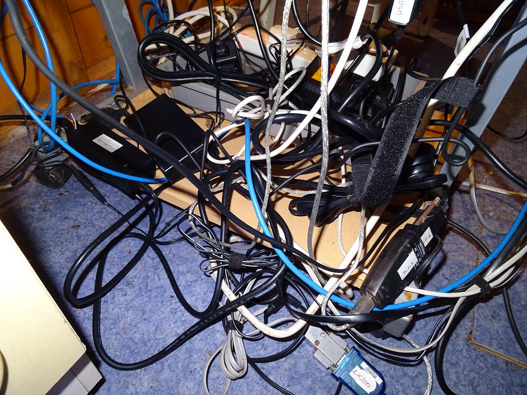
-
Carefully plan out the observatory cabling (240v power leads, 12v power leads,
serial leads, USB leads, ethernet leads)
- Carefully plan out positioning of
work spaces for Observatory Control Laptop, AllSky Laptop and Miscellaneous
Items
2) Pier Block. The existing concrete pier block(which can't
easily be removed) may prevent or cause problems during the construction of a
new concrete pier block (Note: an elevation difference to the concrete pad
required for the new dome observatory, and a desire to move the observatory
slightly further away from boundary fencing prevents reuse of existing pier
base). The new pier block may end up directly abutting the old pier block.
WHilst this might help support the new pier, it may also lead to unplanned
transfer of vibrations when walking or moving about on the concrete observatory
floor which in part lies on the old pier block.
Proposed Solution
- Offset the New Observatory from the old
observatory by a sufficient distance so that a new pier base can be dug without
significant impact from the old concrete pier base. The new base will
effectively sit alongside the old pier base.
3) GPS Fix. LX200 may not be able to get a GPS fix (including accurate time)
at start up and may effectively 'hang' whilst it searches in vain for a gps fix.
Based on the occasions when the TS APO 80mm
guidescope has been accidentally mounted before powering up the LX200 this will
almost certainly be a problem when the guidescope is permanently left attached to the LX200 main scope between sessions
in new observatory. The fibreglass dome itself may or may not hinder getting a
gps fix. Since the observatory is at a permanent site, not getting a
gps fix at start-up is not a particular problem since site coords get are saved
for the site in Autostar II. However getting a gps fix is a very convenient way
to ensure that the LX200 operates during the session with an accurate date/time
since date/time are not preserved through power down/power up cycles. Manually
entering date/time is a big inconvenience.
Proposed Solution
- Disable GPS On LX200 (done from Autostar II
menu). Note this also disables the acquisition of Date/Time.
- Change 'Auto
Set Time' setting in LX200GPS/R Ascom Driver so that scope time is always set to
computer time upon connect.
- Change Start-Up procedure
- Update Computer Time from Internet at the start of or just before start of the
session
- Turn on LX200 (GPS disabled)
- Connect to LX200GPS/R via POTH-Hub & LX200GPS/R ASCOM driver (scope time set
to computer time)
- Check that Telescope's coordinates
match those expected.
(An alternative solution would be the
purchase and installation of a GPS repeater, positioned so that its internal
transmitter lay close to the GPS reciever in the LX200's left-hand fork arm)
4) Dome Aperture. LX200 main scope and/or TS 80mm APO secondary scope might not be able
to see out through the Dome Aperture when pointing in particular directionns.
Pointing at zenith or just beyond zenith is a particular problem as the shutter
can only be pulled back some 15-20cm beyond zenith.
Proposed Solution
- Install Pier some 15-17 cm south of dome centre to enable 80mm scope to still
see the sky when main scope is pointing near to zenith (with shutter open to the
south), but still allows the main scope to see the sky when pointing beyond
zenith (with shutter open to north)
- Use POTH Hub to synchronise the pointing of the dome
with that the main telescope. The algorithum is understood to take into account
the position of the scope's RA/Dec Axes recorded in setting as well as the
altitude and azimuth that the scope is pointing to.
5) Condensation. Condensation is reported to be a potential problem in
Fiberglass Dome Observatories
(even though exposure to dew and/or
frost will be less than existing roll-off observatory)
Proposed Solution
- Monitor situation to see if condensation turns out
to be a real
problem or not. (I personally think the humidity levels will be
lower than the roll-off observatory -
- If required, purchase a de-humidifier to
reduce humidity & prevent condensation
(Humidifier will require the
following features: Desiccant dehumidifier, Continuous
drain facility , Humidistat)
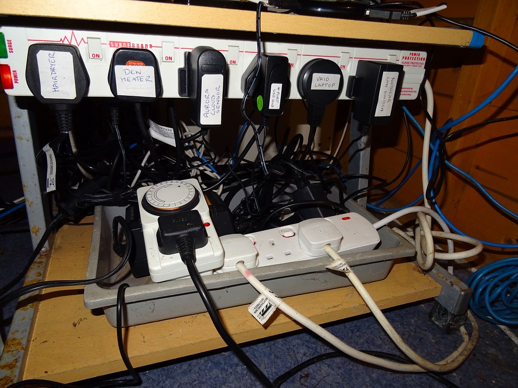
6) Power Overloading. Total observatory power requirements might
exceed 13A fuse rating on the main plug serving the observatory due to the addition of extra equipment
associated with the New Observatory (a) Rigel Dome Rotation Drive & Induction
Charger for Shutter Drive, b) a Focuser for 80m APO scope and c) a
Dehumidifier)
Proposed Solution
-
Firstly understand if there is a problem here or not, by compiling list of all
equipment to be used and the wattage and power amperage draw of each item at
240V equivalent, and finally by calculating the summed amperage draw (assuming
all equipment ws being used simultaneously) and compare against the 13A limit.
- Initial assessment indicates maximum observatory power consumption is 1728W (7.2A
@ 240V),
excluding hairdryer & assuming a 50% power efficicieny on AC adapters, or 3328W
(13.9A @ 240V) including hairdryer.
- Hairdryer (1600W, 6.6A) is the single most
power-hungery item of equipment in observatory and should only be used when
other equipment isn't drawing high current (i.e. when telescope & dome is
stationary and camera & focusers are paused). In event of problems dew heater
should also be temporarily turned down or turned off whilst using the hairdryer.
- Dehumidifier should be switched off during observing sessions to reduce power
load
- Follow up initial assessment with a more accurate assessment using a Power/Voltage/Amps/Watt Electricity Usage Monitor with
Digital LCD Display (which can be easily purchased through Amazon for £16 or so)
Back to Top
| Power | Direct | Indirect | ||||||
| Set | Equipment | Sockets | Ethernet | Serial | USB | USB | Notes | |
| Set 1 | Observatory Computer | 1 | 1 | (3) | ||||
| Set 1 | Computer Mouse | 1 | ||||||
| Set 1 | Dome Controller | 1 | 1 | |||||
| Set 1 | LX200 Telescope | 1 | 1 | 1 | USB to Serial | |||
| Set 1 | SBIG Camera | 1 | 1 | |||||
| Set 1 | Optec TCF-S Focuser | 1 | 1 | 1 | USB to Serial | |||
| Set 1 | ASI178MC Camera | 1 | ||||||
| Set 1 | Dew Heater | 1 | ||||||
| Set 1 | USB Hub 1 | 1 | 1 | (4) | ||||
| Set 2 | AllSky Laptop | 1 | 1 | (2) | ||||
| Set 2 | Computer Mouse | 1 | ||||||
| Set 2 | AllSky Archive Drive | 1 | ||||||
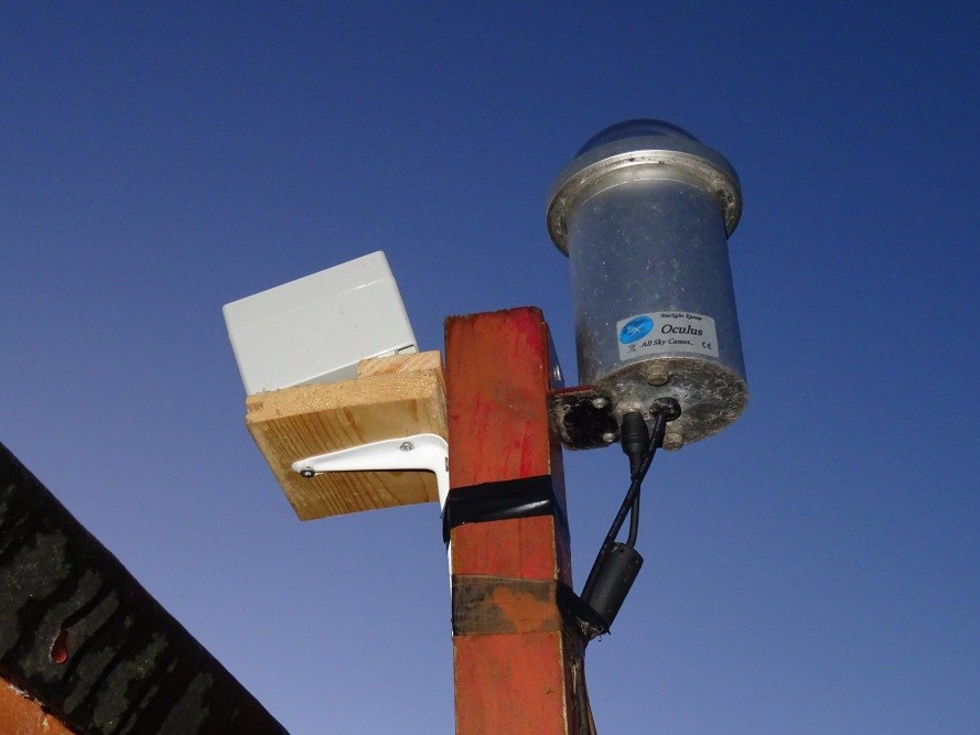
| Set 2 | Oculus AllSky Camera | 1 | 1 | |||||
| Set 2 | Oregon Scientific Weather Stn | 1 | ||||||
| Set 2 | Aurora Cloud Sensor | 1 | 1 | 1 | USB to Serial | |||
| Set 2 | USB Hub 2 | 1 | 1 | (4) | ||||
| Set 3 | Ethernet Hub | 1 | ||||||
| Set 3 | General | 1 | Hairdryer / Flat Frame Sheet | |||||
| Set 4 | Light | 1 | ||||||
| Total | 14 | 2 | 3 | 11 |
Initial assessment indicates a maximum total observatory power consumption of 1728W (7.2A @ 240V), excluding hairdryer & assuming a 50% power efficicieny on AC adapters, or 3328W (13.9A @ 240V) including hairdryer. Hairdryer (1600W, 6.6A) is the single most power-hungery item of equipment in the observatory and should only be used when other equipment isn't drawing high current.
Back to Top
Between 2015 and 2017 an always-on 'AllSky laptop' situated in the observatory has been used to control the capture and processing of AllSky Images, between sunset and sunrise each night. During observing sessions (but not in between times) the 'House Computer' captures weather station data (temperature, humidity, wind and pressure) and the 'Main Observing Laptop' captures sky temperature, cloud and rain data when it's operating an observing session and the observatory the roof is open (exposing Cloud Sensor to the night sky).
In the New Observatory it is intended that the 'AllSky laptop' takes on the role of capturing all weather and environmental data on a 24x7 basis, distributing this data to the 'Main Observing Laptop' as required.
A number of things have begun to happen to make this possible:
1) A serious bug on AllSky imaging control program has been fixed and allows
the AllSky laptop to run 24x7 without the AllSky Program and/or the laptop
crashing.
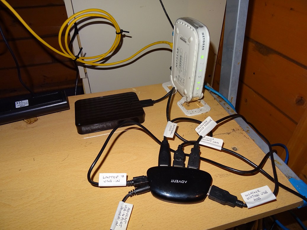
2) A 4-port USB hub has been bought and connected to one of the
two USB ports on 'AllSky Laptop'. The 4 ports will be used for
a) Mouse, b) Oculus AllSky Camera, c) USB Communication Hub for talking
with WMR180 base station d) Aurora Cloud Sensor
3) The USB Hub can be powered, but it is not yet known whether it will
actually need to be powered or not, as the only device definately needing
additional power is an external USB hard drive (used for Archiving AllSky
images) which will be run directly from the other USB port on the laptop.
4) Weather Station program (VMS), USB Communication Hub and my weather data
repeater program have been installed on the 'AllSky' Laptop and have run for 10
hours plus. Testing continues but so far the VMS program running on
'AllSky laptop' has been shown to be able to succesfully access and read weather
data from the WRM180 base station sitting on my kitchen window sill, and
forward data to the Observatory Control Laptop (for recording and information
purposes) and to the AllSky Control Program (for annotating processed AllSky
Images)
5) Addition of Graphs to VWS Display to show the desired weather information, and change Jpge file settings to output Jpg files at regular intervals (say every 20 minutes). A repeater program is then required to transfer weather graphs to the Observatory Control Laptop and/or upload to website (via FTP). This facility being unavailable within the basic edition of the VWS program that I have.
6) Aurora Cloud Sensor Program (v2 and v3) and Driver for Prolific PL2303 USB-to-Serial Adapter have been successfully installed on the AllSky Laptop, and have run for 10 hours plus. A repeater program is required to forward Cloud and Rain Information to the Observatory Control Laptop (for recording and information purposes) and to the AllSky Control Program (for annotating processed AllSky Images & Charts).
7) Move Aurora Cloud Sensor Head from inside the observatory to a position outside the observatory (to allow full-time access to the open sky). Cable length is easily long enough, but the method of fixing the Sensor Head outside needs to be defined.
8) Extend routine in AllSky Program to access and display Sky Clarity and Rain data on existing NightSummary Brightness Plot.
9) Develop routines to use weather data to optimise telescopic imaging and observations and protect Dome and equipment from rain or high winds but closing the Dome's shutter at first sign of adverse conditions.
10) Consideration may need to be given to future options such as adding a new CMOS camera & fisheye lens capable of taking both daytime and nighttime AllSky colour images.
Progress in ongoing. Pictures shown below.
Back to Top
Provisional Cabling Plans for new observatory are shown below:
| Telescope Control and Imaging - option 1, based on existing setup |
 |
| Telescope Control and Imaging - option 2, based on using an Altair all-in-one solution (Pegasus PowerBox & USB Control Hub ) |
 |
| Observatory Bay 1 - AllSky Imaging, Weather, Ethernet Hub, Power Board |
 |
| Observatory Bay 1 - Power Panel and Dome Drive System |
 |
| Observatory Bay 1 - Power Panel and Dome Drive System |
 |
Altair Pegasus
Use of an
Pegasus Ultimate PowerBox USB Control Hub (Altair), or similar system, could
offer me a chance of reducing the cabling going to the telescope. Cost for the
Alatir all-in-one solution is however pretty high (£499) and its not
certain whether it can be justified or not. It would be used
- dew heater
control (2)
- power for focusers (2)
- USB cable to focusers (2)
- USB
cable to ST-10XME camera (1)
It doesn't remove the need for a serial cable to Optec TCF-S Focuser, and may require the Focus Control/Handbox Unit to be mounted on the scope itself, rather than on the pier as at present.
The unit offers no significant benefits however with regard to
-
power for ST-10XME camera (ST-10 uses a special 12V, 12V, 5V AC Adpater
adapter and 5 pin power cable
- power for LX200 (this is can be more
easily supplied by cabling from the pier)
- control cable for the LX200
(this is more easiy supplied by RS232 cable (serial to USB) from the pier
-
USB cable to the ASI178MC camera, which requires a direct camera to computer
connection to achieve the highest possible frame rates
The number of cables going to the Telescope Tube area (serving Imaging
Cameras, Dew Heaters and Focusers) reduces from 7 to 4. This is a saving of 3
cables but at the expense of having extra kit (Optec TCF-S handbox and the
Pegasus Control Hub) attached to the telescope tube/forks by some means.
The Pegasus would also reduce the number of required 240v power sockets by
2.
Back to Top
| This Web Page: | Notes - New Observatory (2018) |
| Last Updated : | 2018-01-08 |
| Site Owner : | David Richards |
| Home Page : | David's Astronomy Web Site |