David's Astronomy Pages
Notes - Session 635 (2018-10-30)
Notes
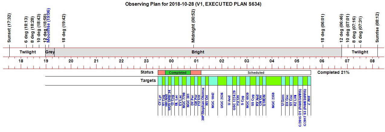
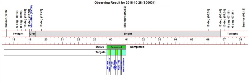
(S634)
Notes
Main
Home
Page
Notes
(S636)
David's Astronomy Pages
|
Notes (S634) |
Notes Main |
Home Page |
Notes (S636) |
Main aims
Equipment & Software
Highlights
Summary Plots & Logs
|
Observing Result (2018-10-30, S635) USB Hub Installed and Tested at ~16:40. Session initially began at 18:13 Problems seeing LX200 GPS/R through COM13. Eventually connected with LX200 through COM3 at 18:51 Delay whilst weather conditions improved. TheSky6 lost connection with LX200 at 20:40, LX200 restarted. Session on auto from 23:27, Equilibration not started till 23:40 (due to weather) Job Queue started at 23:44. Communication with SBIG Camera failed at 00:40. Job queue aborted at 00:57 Session ended at 01:15 (scope/dome parked manually) . |
 |
|
(Observation Status : Green=Completed, Yellow=
Partially Completed, Red= Failed) Diagnosed Failures : Missed Start / Weather (x2), Aborted to make way for ToO Target (x1), Camera Failure (x3) Diagnosed Non-Completions : ToO target didn't take image set (x1) |
 |
|
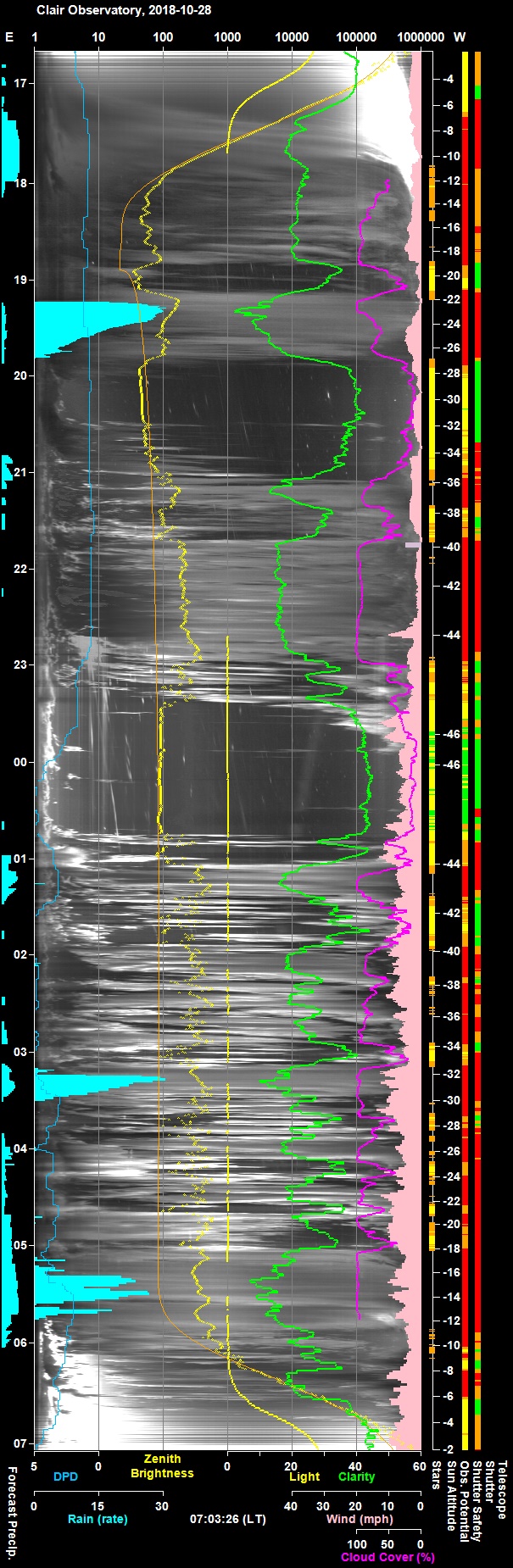
Night Sky Summary Plot -
2018-10-30 Top axis: Sky Brightness at Zenith (in ADU/s) Lefthand axis: Local Time (hh LT). Righthand axis: Sun Altitude (degs) Shutter/Telescope columns missing unfortunatelly (the 'TP Service' was accidently not engaged). |
 |
Back to Top
Illustrations - Screen captures illustrating particular issues from session :
|
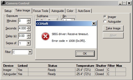
Fig 1: CCDSoft5 Error Message at 20:32 "SBIG driver: Receive timeout. Error code = 1008" |
 |
|
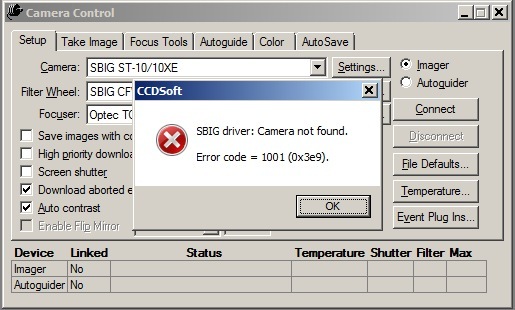
Fig 2: CCDSoft5 Error Message at 20:40 "SBIG driver: Camera not found. Error code = 1001" |
 |
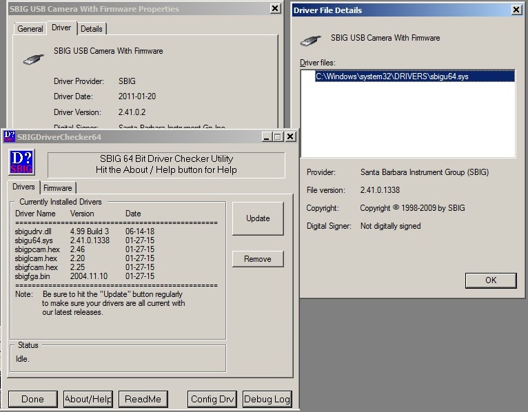
| Fig 3: Updated SBIG Drivers at 20:43 |
 |
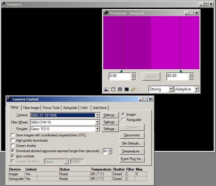
| Fig 4: SBIG downloading empty (single value) Image Files at 21:49 |
 |
|
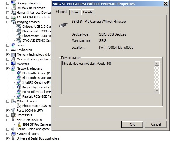
Fig 5: SBIG device can not start (Code 10) at 22:50 (device name appears as SBIG ST Pro Camera Without Firmware, rather the normal name SBIG USB Camera Without Firmware) |
 |
Back to Top
With connection issues with the TCF-S focuser becoming more frequent, and
with the issue not resolved by using a new USB Hub (2018-10-28), the idea
of updating the TCF-S drivers came to mind. Visit to Optec website (
https://optecinc.com/astronomy/downloads/tcf-s.htm ) indicated that latest
version TCF-S Control Program and ASCOM Driver is version
6.0.6. Checking showed that this latest version (
6.0.6) was installed on my computer around 2018-10-08
Reading the vn
6.0.6 download information again it was noticed that for my particular version
of TCF-S Control Box (Rev 3 or 4) the REQUIRED version of TCF-S Firmware is
v2.40. But checking the firmware version number on control box's LED
during initialisation shows that it's firmware is 2.33 .
It is tempting
to think that the connection problems might somehow be related moving to 6.0.6
whilst continuing to use firmware v2.33 (rather than the required v2.40) however
records from Jan 2018, reveal that TCF-S driver was deliberately
upgraded from 5.4.2 (64 bit) to 6.0.6 (any cpu) with the expressed hope of
solving the connections issues already present when using the former driver.
[ Cost of firmware upgrade to v2.40 using a user installable PIC chip is $25 (excl shipping and duty) ]
Querying the situation with Optec , their recommendation was to use the firmware upgrade to 2.40 and use the new Serial cable with integrated USB.
Alternate Plan
Current operation of the TCF-S focuser is performed using
CCDSoft5's focuser connection, with the focuser set to "Optec TCF-S". It is
presumed that operation of the scope is performed use 'raw' commands to the
TCF-S control box rather than via the TCF-S ASCOM driver. (It is
noted that connections to TCF-S are not possible from the Commander program and
from CCDSoft at the same time, which probably confirms that CCDSoft5 isn't using
ASCOM driver which should support multiple connections)
WIth the possibility that the connection issues might be resolved by using ASCOM driver rather than CCDSoft's direct control the potential use of TCF-S Ascom driver from with CCDAp2 (Observatory Control Program) was investigated.
Connecting to the TCF-S Focuser via an ASCOM.DriverAccess.Focuser object, it
was shown that the TCF-S values (Step position etc) could be accessed and that
this was possible to have both this connection and the TCF-S connection from
with the Commander program open at the same time.
Next steps would be to
prove that Focuser can be moved using the .Focuser object, and then fully
transfer CCDApp2 focuser control to using ASCOM connection rather than using
CCDSoft's Camera object.
So instead of getting current focuser position using "Camera.focPosition" (CCDSoft5), the position would be obtained using "objFocuser1.Position" (ASCOM).
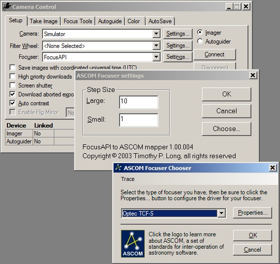
A potential alternate way of operating the TCF-S focuser using CCDSoft5, is to use the "ASCOM Focuser (FocusAPI) Plug-In for CCDSoft" (available from https://ascom-standards.org/Downloads/Plugins.htm ) in order to access the TCF-S ASCOM Driver that way.
Back to Top
Background
Operation of TCF-S focuser for focusing, for
temperature compensated focusing and for filter focus offsets has been
frequently failing part way through a session as connection to the focuser is
seemingly lost.
Access to the 'Optec TCF-S' focuser is made via the CCDSoft5 camera object which uses direct (non-ASCOM) connection to the Focuser. Various things to remedy the lost connection issue (e.g. driver updates, different USB Hub) haven't worked and since there isn't a fool proof method of restarting the connection without rebooting everything the problem is both frustrating and a showstopper for unattended operation of the observatory.
Aim
To operate TCF-S focuser through entire sessions
without the connection being lost, thereby preventing operating outages and/or
poorly focussed images.
Plan
Plan is to try to resolve the lost connection issue
by operated the TCF-S focuser using it's ascom driver instead of direct
(non-Ascom) connection from CCDSoft5.
Whilst this can be
done by creating an ASCOM.Focuser object in my Observatory Control Program
(CCDApp2) and adjusting the references used for interfacing with the
focuser's properties and methods an alternate method required no change to
CCDApp2 program code is to employ the "ASCOM Focuser (FocusAPI) Plug-In for CCDSoft"
in order to access the TCF-S ASCOM Driver that way.
Installation of Plug-In
The FocusAPI Plug-In for CCDSoft
(downloaded from
https://ascom-standards.org/Downloads/Plugins.htm) was installed on Laptop9
(Observatory Computer) and Laptop10 (Development/General Computer). The plug-ins
read me notes are copied below for information.
CCDSoft Focus API Plugin (FocusAPI) V1.0.4

------------------------------------------

THIS FILE
(FocusAPI-ReadMe.txt) IS LOCATED IN PROGRAM FILES\COMMON FILES\ASCOM (on 64-bit
systems, look in "Program Files (x86)")

The FocusAPI plugin provides
CCDSoft with the ability to control focusers via their ASCOM standard drivers.
With this plugin, you can use focusers not supported internally by CCDSoft but
which have ASCOM drivers. Also, some focusers have ASCOM drivers that provide
enhanced functionality as compared to that provided with the internal support in
CCDSoft. You can use such a focuser via its ASCOM driver with this plugin.


One-Time Setup:

1. In CCDSoft, in the Camera Settings pane, set the
focuser to 'FocusAPI'.
2. Click Settings to bring up the focuser settings
dialog. Enter your preferred large and small step sizes.
3. Click Choose...
to display the ASCOM Focuser Chooser.
4. Choose your focuser and click on the
Properties... button to adjust settings.
5. Click OK on all dialogs.
6.
Back in the CCDSoft Camera Settings pane, click Connect. CCDSoft should connect
to your ASCOM focuser.

You will then have access to focuser movement in
the CCDSoft Focus Tools pane, and @Focus should operate the ASCOM focuser.| CCDSoft5 set up to use TCF-S Focuser via ASCOM |
 |
Testing
Operation of the TCF-S focuser was tested using the FocusAPI connection, but
whilst focuser position can be read, and focuser moved from either CCDSoft5 or
my Control Program (using CCDSoft.Camera.focPosition), the temperature
probe reading (using CCDSoft.Camera.focTemperature ) is
unfortunately not implemented in FocusAPI.
With the temperature reading critical for temperature regulated focusing
I’m therefore creating my own ASCOM object and will use that for operating
the focuser (including access to Temperature reading). I will monitor things
over the next few sessions to see if things improve..
Back to Top
- Latest ASCOM Platform (6.4 SP1) was installed on Laptop9
(Observatory Computer, Win7) and Laptop10 (Development/General Computer, Win10).
- The new
platform replaced the previously installed 6.3 platform.
https://ascom-standards.org/Downloads/Index.htm
https://github.com/ASCOMInitiative/ASCOMPlatform/releases
Back to Top
CCDSoft Focus API Plugin (FocusAPI) V1.0.4------------------------------------------THIS FILE
(FocusAPI-ReadMe.txt) IS LOCATED IN PROGRAM FILES\COMMON FILES\ASCOM (on 64-bit
systems, look in "Program Files (x86)")The FocusAPI plugin provides
CCDSoft with the ability to control focusers via their ASCOM standard drivers.
With this plugin, you can use focusers not supported internally by CCDSoft but
which have ASCOM drivers. Also, some focusers have ASCOM drivers that provide
enhanced functionality as compared to that provided with the internal support in
CCDSoft. You can use such a focuser via its ASCOM driver with this plugin.One-Time Setup:1. In CCDSoft, in the Camera Settings pane, set the
focuser to 'FocusAPI'.2. Click Settings to bring up the focuser settings
dialog. Enter your preferred large and small step sizes.3. Click Choose...
to display the ASCOM Focuser Chooser.4. Choose your focuser and click on the
Properties... button to adjust settings.5. Click OK on all dialogs.6.
Back in the CCDSoft Camera Settings pane, click Connect. CCDSoft should connect
to your ASCOM focuser. You will then have access to focuser movement in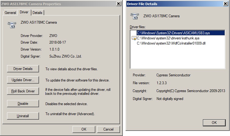
the CCDSoft Focus Tools pane, and @Focus should operate the ASCOM focuser.Latest ASI Camera Native Driver (v3.0.0.5) was installed on
Laptop9 (Observatory Computer) and Laptop10 (Development/General Computer).
On Laptop 9 the driver replaced the previous installed driver v1.3.12.28 , which
had be manually uninstalled first
On Laptop10 the driver was a new fresh
install
Latest ASI Camera Ascom Driver (v1.0.3.22) was installed on
Laptop9 (Observatory Computer) and Laptop10 (Development/General Computer).
On Laptop 9 the ascom driver replaced the previous installed driver v1.0.2.13 ,
which had be manually uninstalled first
On Laptop10 the ascom driver was a
new fresh install
https://astronomy-imaging-camera.com/software-drivers
|
ZWO ASI 178MC Camera Properties with New Drivers (1.0.1.0, dated 2018-08-17) (the previous driver version was 1.0.0.4, dated 2014-11-24) |
 |
System Check ( post ASI Driver Installation)
Native Drivers
- Equipment Profile (ZWO ASI178MC) created to test
use of existing native ASI Camera drivers for operating the ASI178MC camera
- Camera: "ASI
Camera", Mount: "Telescope Simulator
for .NET (ASCOM)" (temporaily standing in for POTH.Hub)
- Quick Test: Connection ok,
Camera Imaging ok
- New Equipment Profile (ZWO ASI ASCOM Cam) created to test
use of ASCOM drivers for operating the ASI178MC camera
- Camera: "ASI
Camera (2) (ASCOM)", Mount: "Telescope Simulator
for .NET (ASCOM)"
- Quick Test: Connection ok,
Camera Imaging ok
Back to Top
Aim
One of the key components for reliable unattended
operation of the Observatory is robust autoguiding under automated control.
Current Situation
PHD2 software is used for autoguiding
as it does the job well and can be controlled via OpenPHD2 communication (for
turning guiding on before imaging a target, for monitoring the guiding
performance during imaging and for turning the guiding off once a target has
been completed). PHD2 performance is good when the stars are
well focused, but deteriorates badly when stars are out of focus with the
tendancy of PHD2 to pick a very dim guide star / hot pixel and/or quickly lose
star lock due to star mass changes.
Guiding uses a ZWO ASI178MC camera
attached to a TS 80mm APO scope piggybacked on top of the main LX200 scope.
Up to now focusing of the guidescope has to be done by the manual
manipulation of the TS 80mm APO scope's focuser knobs whilst watching the
looping image in PHD2 and observing the FWHM/HFD values associated with a guide
star. This is both tricky and not consistent
with the intended move towards fully remote and/or fully automated control of
the observatory (If star is a long way from focus it is particularly difficult
to find focus from within PHD2)
To assist the process a motor focus with
computer connected focus controller (Pegasus Ultimate Powerbox) will be added at
the scope. This leaves the issue that PHD2 doesn't have it's own facility
for focusing a scope based on the images it captures. Whilst remote
control of the focuser, whilst watching the image & FWHM/ HFD values in
PHD2 is a step forward from , this is far from ideal.
Plan
The use of a second program (not yet defined) is
needed to carry out the auto-focusing task either at the start of session or at
any time during the session if focuser drifts beyond what standard Temperature
Compensation can handle.
Up to now PHD2 has been set to use direct (native) connection to ASI Camera (ZWO ASI178MC). This precludes using another program being connected to the Camera at the same time or causes problems. To get around this limitation it is proposed that connection to the ASI Camera is made via ASCOM Driver.
Proof of Concept
To test the plan a new PHD2 Equipment
Profile was created which was set to use "ASI Camera (1) (ASCOM)" whilst
CCDSoft5 was set to use "ASCOM Camera" set to use "ASI Camera (1)". Tests
showed that it was possible to have both connections open at the same time and
to take images from both PHD2 and CCDSoft5 provided that imaging wasn't
performed at the same time.
If PHD2 was looping images and an CCDSoft5
made an attempt to take a frame, it was found that CCDSoft wasn't able to
download the image, and the Image had to be aborted otherwise Camera would be
stuck trying to download the image. Similarly if PHD2 tried to loop images
whilst CCDSoft was looping images both programs would have problems - CCDSoft
would stall whilst trying to download an image, PHD2 would stall and timeout
after 16sec of trying to take a frame.
A further test was conducted where CCDApp2 (Observatory Control Program) was also connected to "ASI Camera (1)", making a total of 3 connections to the camera Whilst CCDSoft5 was looping images, CCDApp2 was able to successfully read a series of camera properties (Driver Information, BinX, BinY, Gain, CCDTemperature).
[ Camera connection is made using the ASCOM ID: ASCOM.ASICamera2.Camera. It's not understood why ".ASICamera2." name is used for ASI Camera (1) ]
Back to Top
A key factor in successfully programming involving access to ASCOM drivers is
to know the precise Properties & Methods to use for each NameSpace.
One way of getting an overview and detail is to use the DriverAccess Namespace
pages on the ASCOM Standards website.
DriverAccess Namespace
NameSpace for ASCOM Driver Access is described on at
https://ascom-standards.org/Help/Developer/html/N_ASCOM_DriverAccess.htm
Back to Top
Reliable telescope operation is critical to observatory operations. Recent occurances of "ASCOM Utilities : Timed out waiting for received data" error message during sessions over the last 6 months present a showstopper for unattended operation of the observatory, as the dialog box needs to be manually dismissed before remedial fixes such as disconnecting/reconnecting the Scope from TheSky6 can be performed.
|
TheSky6 Error Message: "ASCOM Utilities : Timed out waiting for received data" |
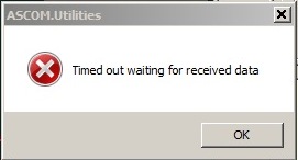 |
It is understood that the message appears when ASCOM is waiting more than 5 secs and it timesout.
Looking at the ASCOM Talk forum (IO Groups) and 'StarGazersLounge'
forum a suggested fix for the problem
is to run Autostar Garbage Collection to 'clean' the memory in Autostar ..e.g
https://stargazerslounge.com/topic/311415-help-meade-lx200gps-ascom-phd-issue/.
Andrew Johansen's MyScope program was highlighted as one particularly suitable
tools for doing Garbage Collect.
Autostar is understood to use a
linked-list data structure, and does not erase old entries until a Collection
operation is performed... eventually the time required to traverse a long long
list of expired entries exceeds ASCOM's timeout of 5 secs. With a clean list,
LX200GPS response time is under 2 secs)
Andrew Johansen's
MyScope
software can be found at
http://members.optusnet.com.au/johansea/
Garbage Collection is found
under 'List Data' / 'Menus' / 'Garbage Collect'
(Unfortunately I was unable to get the associated .hlp help file to be
displayed in either Window7 or Window10. Some research online suggested viewing
the .hlp help files might require installation of Windows Help
program (WinHlp32.exe) for Windows 7" from
https://www.microsoft.com/en-gb/download/details.aspx?id=91 I tried
this on Windows 7 machine but I still couldn't get the help file to display.
Back to Top
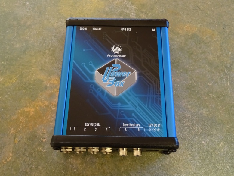
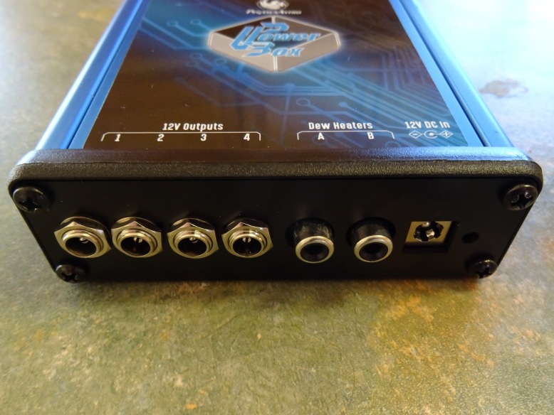
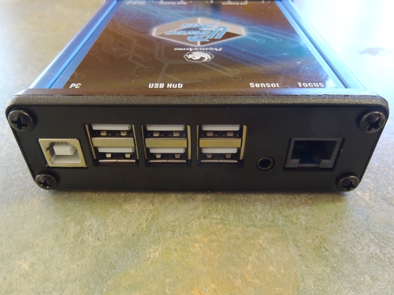
Arrival
Pegasus Ultimate PowerBox arrived today from
AltairAstro and was quickly unpacked.
(The accompanying
Universal Motor Focus was missing a Serial Cable and will be sent to me later.
Cable arrived o 2018-11-06)
Software
Powerbox-Setup-1.4.9 was installed on installed
on Laptop9 (Observatory Computer) along with 3 ASCOM drivers:
Pegasus UPB
Switch Setup 1.3, Pegasus UPB Focuser Setup 1.1 & Pegasus UPB Env Setup
1.3
Powerbox Setup and the 3 ASCOM drivers had been already installed
on Laptop10 (Development/General Computer) as part of earlier evaluation of the
Ultimate PowerBox and its supporting software
(Software downloads from https://pegasusastro.com/support/).
First few days spent trying to overcome some initial teething issues and get it brought into operation and get its control integrated into my existing Observatory Control Program.
| Pegasus Ultimate Power Box |
 |
 |
 |
The next few days were spent getting accomstomed with the PowerBox connected
to Observatory Computer and other hardware (TCF-S focuser, SBIG Camera)
Problems with dropped connection to the PowerBox caused by a breaks in the cigar
plug power connection and switching of COM Port to new COMP ports numbered were
troubling to track down. After a few days the system eventually settled
down, and the scope was mounted on the LX200's right hand fork arm
A Motor Focus (PEG-MF3-MOTOR-UN) was fitted to the secondary scope on 2018-11-06 / 2018-11-07
Program Settings (Regedit)
HKEY_CURRENT_USER\Software\VB and VBA Program Settings\Pegasus\UPB
serialport : USB Serial Port (COM6)
Getting SID for current user name
In cmd.exe
$ wmic username where name = "Username" get sid
Back to Top
After changing A/C Plug positions in the observatory, power to the Observatory Laptop was accidently left off whilst Pegasus UPB (AutoDew On), SBIG Camera, TCF-S Focuser, Pulsar Dome were running along with the Observatory Control Program (CCDApp2, in monitoring mode) , TheSky6 and CCDSoft5 A Simulation Scope was connected instead of the running. Observatory Dome was connected, as was a simulation Telescope.
After 2 to 3 hours the laptop's battery became depleted to the level that the laptop went into hibernation. When remote connection dropped out, a visit to the observatory was mode during which the power to the laptop was turned on again and the laptop allowed to resume from hibernation.
Initial throught was that after resuming from hibernation was that COM4 Port to the Ultimate PowerBox (UPB) will probably have swapped itself for a higher numbered port (similar to behaviour observed with the PowerBox during initial testing) , and the UPB software would have lost connection to the UPB Box. But this was the not the case, UPB Software connection with the UPB Box was working fine.
Other parts of the system faired less well, in particular the connection to SBIG Camera from CCDSoft5, where attempts to reconnect to the camera would produce the error message "SBIG driver: Camera not found". Deleting SBIG drivers and trying to install updated drivers didn't fix things. Turning off all USB Port / Turning-On all USB Ports didn't fix things either. Eventually the problem was solved by Disabling and
Back to Top
After some problems with COM Ports on Observatory Computer (Laptop9) in
recent days, including an issue with COM4 that was being used by a newly
installed Pegasus Ultimate Power Box (UPB) , the existing set of ports was
thinned down to just those being used by current observatory devices.
This was done by creating a new environmental variable
"DEVMGR_SHOW_NONPRESENT_DEVICES" from 'System properties / Advanced
/ Environmental Variables / New' and setting it to the value 1 (one). Then
from Device Manager goto View and toggle on 'Show Hidden Devices' .
All assigned ports whether connected or not will then be shown.
Any ports that are not needed can be deleted by right clicking the port and selecting Uninstall.
COM4 >> COM6
The (FTDI) USB Serial Port used by UPB was then reasigned
from COM4 to COM6 in case earlier problems have been caused by
conflicts on COM4.
This was done going to the 'USB Serial Port (COM4)'
Properties and going to 'Port Settings / Advanced' and selecting the required
new COM Port from the list of available COM Ports, in this case COM6.
By a similar process the COM Port used by LX200GPS Scope was moved to COM10
| Device | COM Port | USB-Serial Connection | ||
| - | COM3 | Prolific USB-to-Serial Comm Port | ||
| TCF-S Focuser | COM5 | Keyspan USB Serial Port | ||
| UPB PowerBox | COM6 | USB Serial Port (FTDI) | ||
| Pulsar Dome | COM9 | USB Serial Port (FTDI) | ||
| LX200GPS/R | COM10 | Prolific USB-to-Serial Comm Port | ||
| - | COM13 | Keyspan USB Serial Port |
Other non-serial devices are
| Device | Device Name | Type | Type | Note | |||
| ASI178MC Camera | ZWO ASI178MC Camera | USB | Imaging Device | ||||
| ST-10XME Camera | SBG USB Camera With Firmware | USB | SBIG USB Devices |
Back to Top
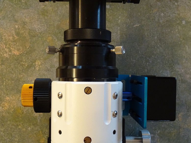
The addition of a Pegasus Universal Motor Focus
Unit (PEG-MF3-MOTOR-UN) to my TS 80mm APO secondary scope in a part of
a set of hardware upgrades to the Clair3 Observatory to widen it's capability
for remote and semi-automated operations and increase its potential for fully
unattended operations.
Key Points:
- The Motor Focus was bought from AltairAstro (UK) and arrived on 2018-11-01 (with
its control cable arriving a few days later, 2018-11-05 )
(the Unit
came with a selection of different Coupling Cylinders, to use with different
shaft diameters)
- The
Motor Focus has a High Resolution Stepper Geared Motor Enclosure (Step Angle
7.5, Deg 120, Gear Ratio 1:120). It's gearbox has very low backlash and high
torque suitable to focus in micron scale. The Motor Focus comes with a Universal
Anodised Aluminium L-shaped bracket for fitting the motor focus to the
telescope, together with a range of motors couplers and associated grub screws.
0.06 degree step size that can easily lift more than 6 Kg of payload. Maximum
Speed 400 (? steps/sec)
- The Motor Focus is being installed on the Rack and Pinion Focuser of my TS 80mm APO refractor which is piggyybacked onto my main scope. The 80mm refractor has several roles including guide scope, secondary deepsky scope, lunar scope & solar scope) . The scope is used with a ZWO ASI 178MC colour camera that is connected via USB3 cable back to the Observatory Computer.
- the Motor Focus will be connected via control cable to the RJ45 focuser port on the Pegasus Ultimate PowerBox (UPB) which has an inbuilt stepper focus controller. Controller supports absolute focusing and it stores the exact focuser position so it can be retrieved in the next observing session.
- The UPB Box is connected to Observatory Computer via USB 2.0 cable where focusing operations are performing using the UPB Control Program, or by my Observatory Control Program (CCDApp2) or other 3rd Party Client Program using ASCOM.
Installation
Installation began with an initial fitting (2018-11-06) in which the focus motor was fitted to the fine focus shaft. This produces unsatisfactory results and the following the day (2018-11-07) the focus motor was refitted onto the coarse focus shaft, which worked much better.
Initial Fitting (2018-11-06)
The 80 mm scope was temporarily removed from the Losmondy style D-Rail that
sits onto for my 12" LX200GPS/R telescope, and brought indoors for the fitting.
It was the intention to the fit the focuser to the shaft on the left hand side
of the RAP Focus system, however in the event I couldn't find a way of taking
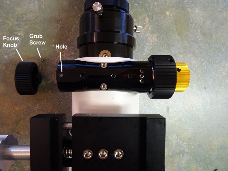
off the single coarse focuser. Unable to find a grub screw on the
knob itself, a grub screen on RAP focuser base close by looked promising .
However loosening/removing the grub screw had not affect at all on loosening the
focus knob. Twarted by this, attention turned to the Dual Focus Knobs on
the left hand side of the focuser, whilst these were removed fairly easily by
loosening 1 grub screw on each.
None of the supplied couplers
allowed me to connect to the coarse focus shaft (not larger enough or
insufficient shaft length to be attached) . After considering the situation I
resigned myself into fitting the Motor Focus onto the fine focus shaft, though
its not recommended as it makes focusing movements very slow.
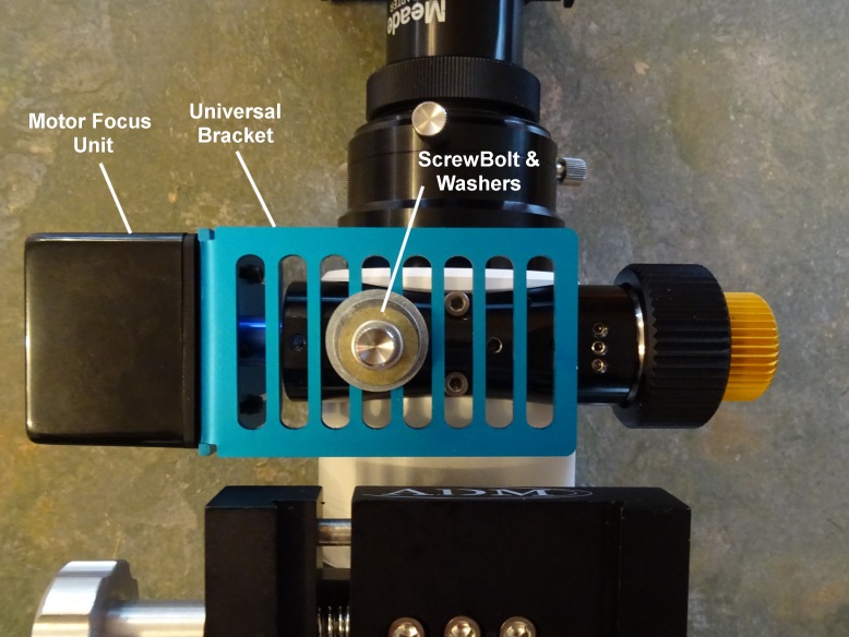
After adjusting the Motor Focus Box's position on the L-Shaped adapter it was fitted to the RAP Focuser of the 80mm scope by means of the coupler and a bolt+washers on the base.
The scope, with installed Motor Focus, was then returned to its position on its Losmondy D-Rail (atop the 12" LX200 SCT Scope)
The direction of movement and a rough rate (steps/cm) was established by
position stepping (+vs steps lengthen the tube (ie. focus out)
and . Focus was manually moved to a working maximum position
about 5mm short of the absolute mechanical maximum and it distance recorded.
Focus was then manually moved to a working minimum position
about 2-3mm short of absolute mechanical minimum and again the distance
recorded (to allow this the grub screws holding the coupler to the Focuser shaft
was loosened, and then tightened after manual moves had been finished).
Using UPB Control Software the Focuser Position was set to 0 at the minimum
working position. Goto moves were submitted to move the scope to
approximate half way point (200,000) and to working maximm position (400,000).
The min/max position were recorded in the UPB focus control tab.
'Position Limit' checkbox was toggled on and an attempt made to move to
position 100 steps beyond the max position. Focuser followed the
instruction and moved to a position 100 steeps greater than max position, rather
than stopping at the max position point. Evidently the 'Position
Limit' can't be relied on in the current version (v1.4.9 / Oct 2018) . The
focus position was then moved to the half-way point 200,000 (taking around 8
minutes to make the move
Based on speed of 400 steps per second and entire travel of 400,000 steps,
this corresponds to 16.7 minutes from Fully-In to Fully-Out positions.
Based
on step size of 0.06deg, one turn of 1:10 fine focus is 6000 steps,
one turn of coarse focus is 60,000 steps. The entire travel
corresponds to 6.7 turns of the coarse focus.)
Unless the speed of making focus adjustments are lowered it will be necessary
to find some way of connecting to the coarse focus shaft which will speed
up operations by x10. Reading some online articals / queries, it
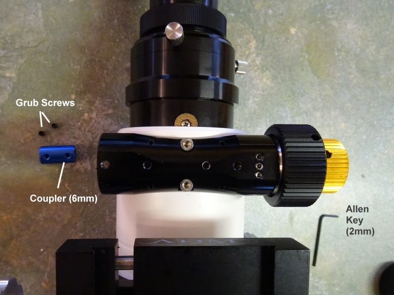
appear that this is possible. Apparently the grub screw next to the single
Coarse Focus Knob, acts as a cover for access to two other grub screws inside
set 90 deg apart.
https://www.cloudynights.com/topic/522910-removing-single-speed-knob-on-wo-star-71-focuser/
Final Fitting (2018-11-07)
The 80 mm scope was again removed from its Losmondy style D-Rail, and brought indoors for the re-fitting the Motor Focus. This was for the purpose of moving the Motor Focus onto the Coarse Focus shaft rather than the Fine Focus shaft where it was initially installed.
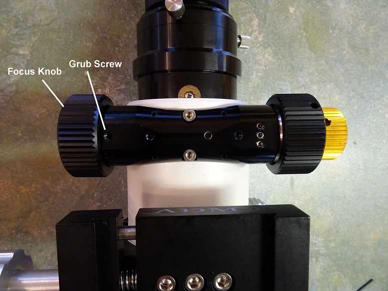
The Motor Focus Unit as removed and the Coarse and Fine Focusing knobs (taken off during the initial motor focus fitting) were refitted.
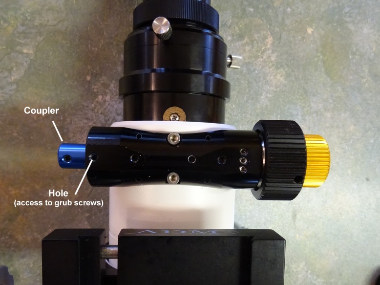
Using the information in https://www.cloudynights.com/topic/522910-removing-single-speed-knob-on-wo-star-71-focuser/ the grub screw next to the single coarse focus knob was removed and then an allen key inserted to loosen two grubs screen on the focus knob, set 90 deg apart, which were holding the focus knob on the main shaft. The knob itself was then easily removed to review the 6mm diameter shaft. A 6mm coupler was then attached to the shaft using two grubs screw, (using the original grub screw portal to tighten them). The Motor Focus and L - shaped adapter plate were then slighted adjusted and the Motor Focus Shaft inserted into Coupler (but not tightened with grubs screws just yet) and bolt/washers used to connect the unit to the bottom of the RAP focuser.
Focuser was moved back to its planned Step 0 position, around 3mm outerside of the mechanical inner limit and the grubs screws were then tightened firmly to connect the shaft of the focus motor to that of the focuser by means of the coupling cylinder. After tightening the coupler the manual focus knobs shouldn't be moved by manual force in case of damage to the gears in the motor focus unit.
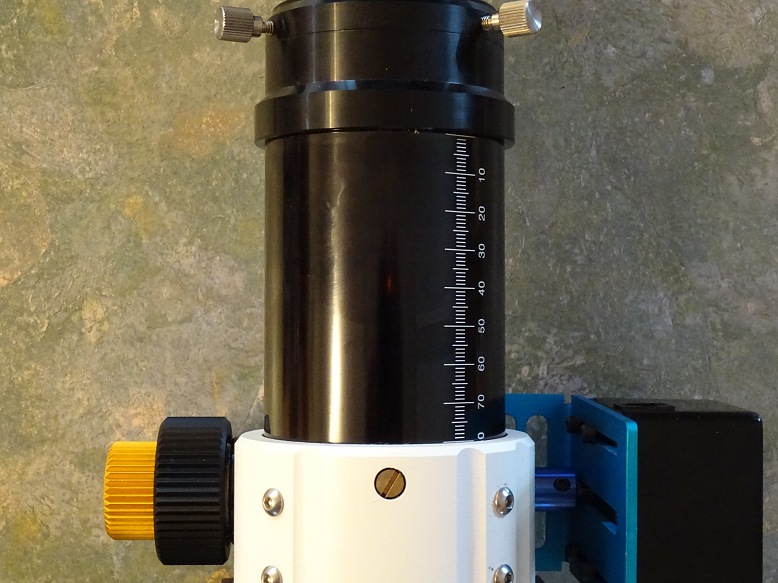
Selecting Safe Inner and Outer Limits |
||
| Tube at Absolute Minimum Mechanical Limit |
Tube at Chosen Minimum (Inner) Limit around 2-3mm outside of the mechanical inner limit (this became the 0 steps position) |
|
 |
 |
|
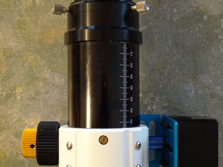
| Tube at Absolute Maximum Mechanical Limit |
Tube at Chosen Maximum (Outer) Limit around 5mm inside of the mechanical outer limit (this became the 40,000 steps position) |
|
 |
 |
|
The scope, with it's re-installed Motor Focus Unit, was then returned to its position on its Losmondy D-Rail (atop the 12" LX200 SCT Scope)
|
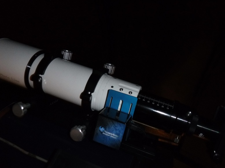
Motor Focus Unit and TS 80mm APO (device attached to back of scope is an Orion XY Finder) |
Motor Focus Unit and TS 80mm APO (night) | |
 |
 |
|
The Control Cable was then attached between the Focus Unit & the UPB Box. After powering up the UPB and checking that the focuser was still sitting at the planned Inner Limit, the UPB Software was used to set the Focuser position to 0 steps. Because the focus motor is now sitting on the opposite side of the focuser to initial fitting it was necessary to select the 'Reverse Motor' option (so that positive steps increments would move the focuser towards the Outer Limit, rather than towards the Inner Hard Stop.
Controls were then used to move the Focuser to the Outer Linit Position which was at 40,000 steps (for the initial fitting this was at 400,000 steps confirming that the fine/coarse focus shafts had a 10:1 turning ratio). The Focuser was then sent to the 0 steps position at the maximum recommended speed (400 steps/sec) and timed. The time, 100 seconds (1m 40s), was consistent with the expected travel time (40000/400).
Based on 72mm working focus range and 40000 steps , each step corresponds to
0.0018 mm and each mm corresponds to 555 steps.
Calculation of the
scope's Critical Focus Zone and
articles covering coarse and fine focusing of the scope using the new Motor
Focus Unit are covered in the notes for the next session (2018-11-07, S636)
Back to Top
| This Web Page: | Notes - Session 635 (2018-10-30) |
| Last Updated : | 2023-11-26 |
| Site Owner : | David Richards |
| Home Page : | David's Astronomy Web Site |
